


M34571T2-CPE User’s Manual 2. Setup
REJ10J0972-0100 Rev.1.00 February 10, 2006 Page 26 of 72
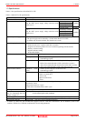
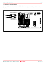
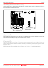
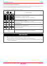
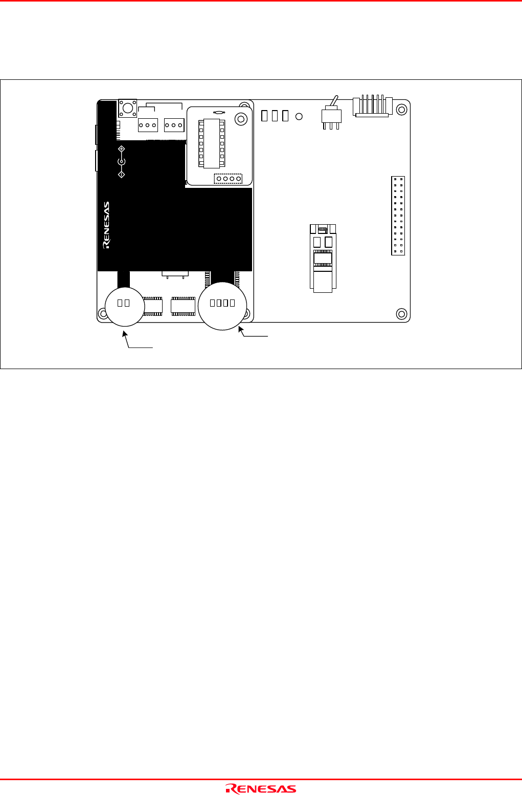
2.5.5 LED Display When the Emulator Starts Up Normally
After the emulator starts up, check the status of the LEDs to see whether the emulator operation is enabled or not. Figure 2.6
shows the positions of the emulator status LEDs.
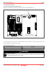
Figure 2.6 Positions of the system status LEDs and target status LEDs
(1) System status LEDs
Check that the LED1 and LED2 of the system status LEDs are lit immediately after the power is activated. If it is not lit, shut
off the emulator and check the power supply for the emulator is properly connected.
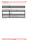
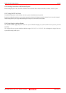
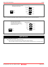
(2) Target status LEDs
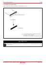
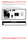
Target status LEDs light as shown in Figure 2.7 when the user system is not connected and as shown in Figure 2.8 when a user
system is connected. When the self-check is terminated after turning the power on, only the LED2 (SAFE) lights on as shown
in Figures 2.7 and 2.8
When the target status LEDs do not display as shown in Figures 2.7 and 2.8, refer to “5. Troubleshooting” (page 65).
System status LEDs
Target status LEDs
M34571T2-CPEB REV.A
TP1
VDD2
GND
TP2
WR ST
POF
LED1
POWER
SAFE
STATUS
J4
3V
5VSW1
J3
13
14
1
26
MADE
POWER
COMPACT EMULATOR
CLOCK
RESET
RUN
LED3
LED6
LED5LED4
POWER
SAFE
LED2
LED1
SAFE
POWER
POWER
CLOCK
RESET
RUN
M34571T2-CPE
STATUS
SYSTEM
STATUS
TARGET
MADE IN JAPAN
COMPACT EMULATOR
POWER
5.0V
USB
POWER
SAFE
LED2
POWER
CLOCK
RESET
RUN
LED3
LED6
LED5 LED4
INT
3.3V 5.0V
JP1
JP2
EXT