


M34571T2-CPE User’s Manual 2. Setup
REJ10J0972-0100 Rev.1.00 February 10, 2006
Page 32 of 72
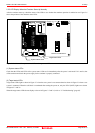
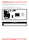
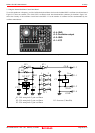
2.8.1 Connecting to a 2.54-mm-pitch Dual in-line Pins
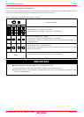
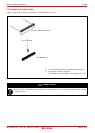
Here following is a procedure of connecting 2.54-mm-pitch 26-pole dual in-line pins using a 26-wire normal-pitch cable
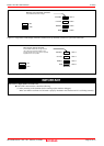
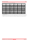
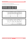
(included with the M34571T2-CPE). Table 2.5 lists the connector assignment of the 26-wire normal-pitch cable and Figure
2.11 shows the pin assignment of the 26-wire normal-pitch cable.
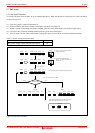
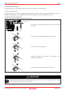
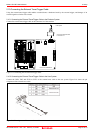
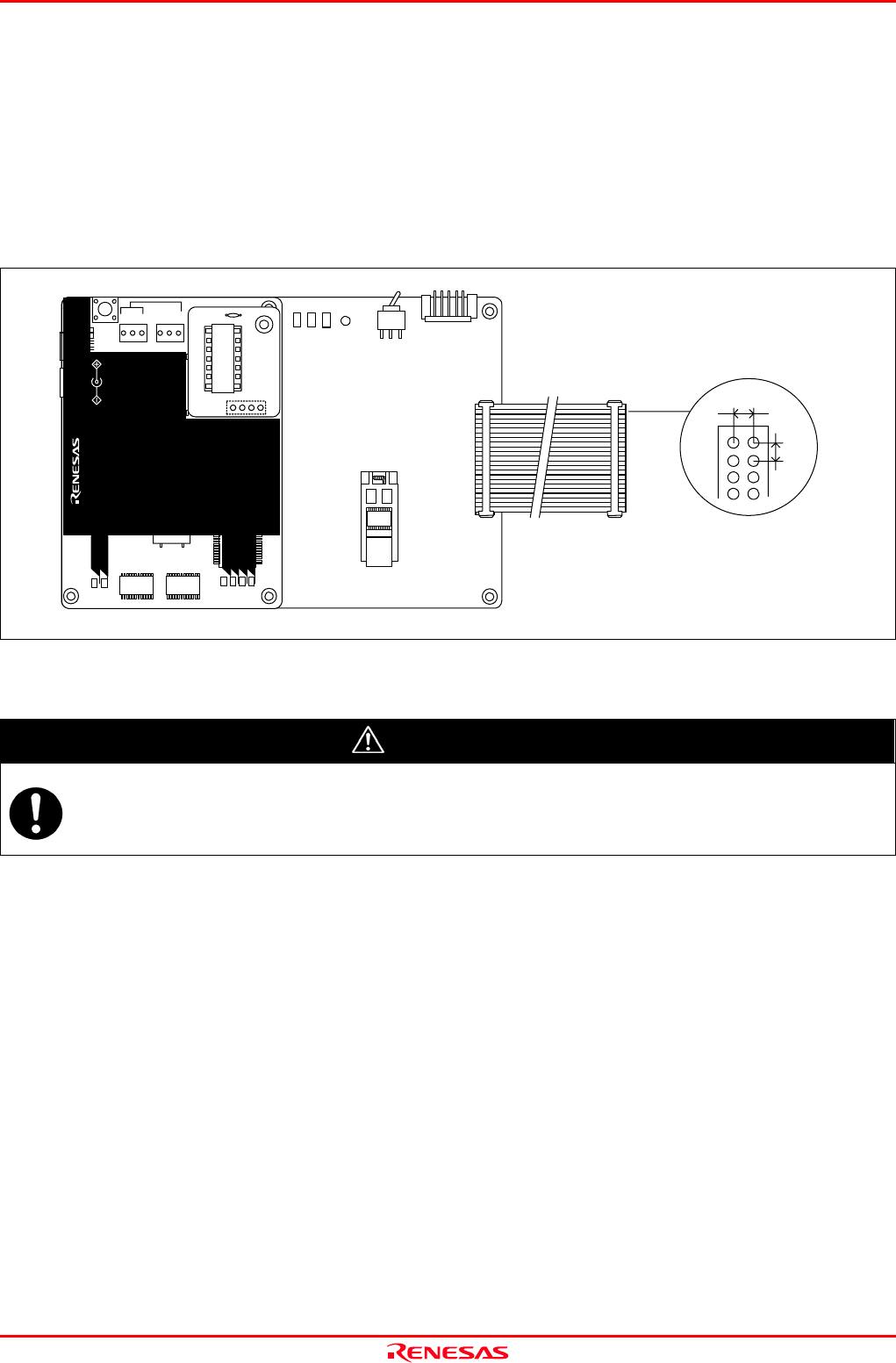
(1) Mount the 26-pole dual in-line pins to the user system.
(2) Attach the 26-wire normal-pitch cable (included) to the J3 connector of the M34571T2-CPE.
(3) Attach the 26-pole dual in-line pins on the user system to the backside of the 26-wire normal-pitch cable.
Figure 2.11 Connecting to a 26-pin 2.54-mm-pitch user system
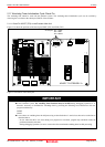
CAUTION
Notes on Connecting the User System:
Take care not to attach a converter board in a wrong direction. It may cause a fatal damage to the emulator and
user system.
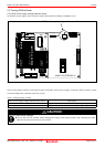
M34571T2-CPEB REV.A
TP1
VDD2
GND
TP2
WR ST
POF
LED1
POWER
SAFE
STATUS
J4
3V
5VSW1
J3
13
14
1
26
MADE
POWER
COMPACT EMULATOR
CLOCK
RESET
RUN
LED3
LED6
LED5LED4
POW ER
SAFE
LED2
LED1
SAFE
POWER
POWER
CLOCK
RESET
RUN
M34571T2-CPE
STATUS
SYSTEM
STATUS
TARGET
MADE IN JAPAN
COMPACT EMULATOR
POWER
5.0V
USB
INT
3.3V 5.0V
JP1
JP2
EXT
1
2.54
2.54
Unit: mm
Omitted
26
26-wire normal-pitch cable