


M34571T2-CPE User’s Manual 4. Hardware Specifications
REJ10J0972-0100 Rev.1.00 February 10, 2006
Page 55 of 72
4.2 Differences between the Actual MCU and Emulator
Differences between the actual MCU and emulator are shown below. When debugging the MCU using this product, be careful
about the following precautions.
IMPORTANT
Note on Differences between the Actual MCU and Emulator:
Operations of the emulator system differ from those of actual MCUs as listed below.
(1) Initial values of internal resource data of an MCU at power-on
With the emulator system, the ROM area at power-on in initialized to 000h (NOP instruction).
(2) Voltage drop detection circuit
Because the operating voltage of this product is fixed to 3V or 5V, it cannot evaluate any system using a
voltage drop detection circuit.
(3) Power-on reset
You can reset this emulator system by the reset command of the emulator debugger M3T-PD45M,
however, this emulator system cannot emulate operation at a power-on reset. Therefore, check the
operation at a power-on reset using an actual MCU.
(4) RESET# output
Because an emulation circuit exists in pin RESET#, systems that use RESET output cannot be evaluated.
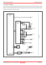
(5) Internal pull-up transistor control
Because this product has an emulation circuit present in ports P0 and P1, you cannot use the MCU's
internal pullup transistors. Therefore, the M34571T2-CPE controls on/off of external pullup resistors
(68kΩ) by decoding the pullup control register transfer instruction (TPU0A and TPU1A).
(6) Unconnected pins
Following pins are not connected to the user system.
Xin, Xout
Note on RESET# Input:
A low input to pin RESET# from the user system is accepted only when a user program is being executed
(when the RUN status LED on the emulator's upper panel is lit).
You cannot use an SRST instruction. If it is executed, it acts as a NOP instruction
Notes on Operating Clock:
The clock generated on the OSC board only is usable as the operating clock, and the clock listed below cannot
be used.
(1) External input clocks on the user system
Clock input to the MCU is supplied from the oscillator circuit board OCS-2 in the emulator, and cannot be
supplied from the oscillator circuit in the user system. If the system clock frequency needs to be changed, alter
the circuit on the oscillator circuit board OCS-2 before use. For details, refer to Section 2.9.2, “Selecting Clock
Supply” (page 35).