


M34571T2-CPE User’s Manual 2. Setup
REJ10J0972-0100 Rev.1.00 February 10, 2006
Page 35 of 72
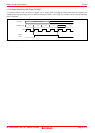
2.9.2 Selecting Clock Supply
This product always uses the internal oscillator circuit as a clock supply to the evaluation MCU.
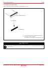
1. Kinds of Oscillator Boards
The M34571T2-CPE comes with an oscillator circuit board OSC-2 (6 MHz). And an oscillator circuit bare board OSC-2 is
included with this product. A clock supplied to an MCU can be changed by replacing oscillator circuit boards.
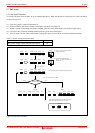
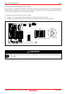
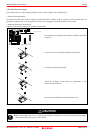
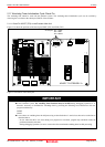
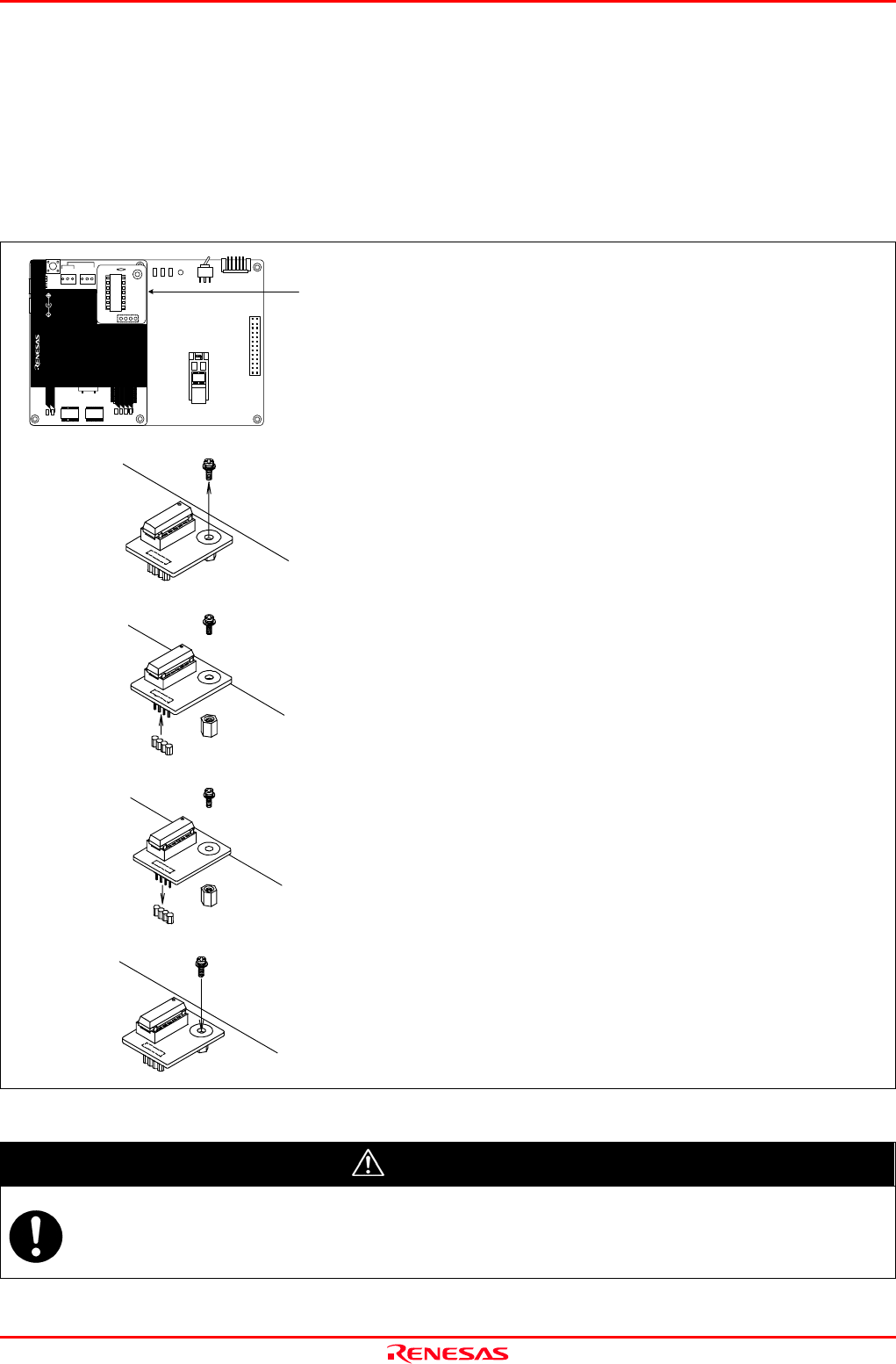
2. Replacing Oscillator Circuit Boards
Figure 2.12 shows how to replace the oscillator circuit boards.
The oscillator circuit board of the emulator is placed as described
on the left.
Unscrew the screw securing the oscillator circuit board.
Lift off the oscillator circuit board.
Attach the oscillator circuit board for replacement to the
connector of the emulator.
Secure the new oscillator circuit board with the screw.
Figure 2.12 Replacing oscillator circuit boards
CAUTION
Note on Replacing the Oscillator Circuit Board:
When removing the upper cover or replacing the oscillator circuit boards, be sure to shut OFF the power supply.
Otherwise the internal circuit may cause a break.
M34571T2 -CPEB REV.A
TP1
VDD2
GND
TP2
WRST
POF
LED1
POWER
SAFE
STATUS
J4
3V
5VSW1
J3
13
14
1
26
MADE
POWER
COMPACT EMULATOR
CLOCK
RESET
RUN
LED3
LED6
LED5LED4
POWER
SAFE
LED2
LED1
SAFE
POWER
POWER
CLOCK
RESET
RUN
M34571T2-CPE
STATUS
SYSTEM
STATUS
TARGET
MADEINJAPAN
COMPACTEMULATOR
POWER
5.0V
USB
INT
3.3V 5.0V
JP1
JP2
EXT
Oscillator circuit board