


M34571T2-CPE User’s Manual 4. Hardware Specifications
REJ10J0972-0100 Rev.1.00 February 10, 2006
Page 54 of 72
4. Hardware Specifications
This chapter describes specifications of this product.
4.1 Target MCU Specifications
Table 4.1 lists the specifications of target MCUs which can be debugged with this product.
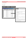
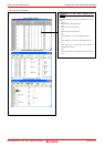
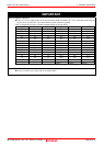
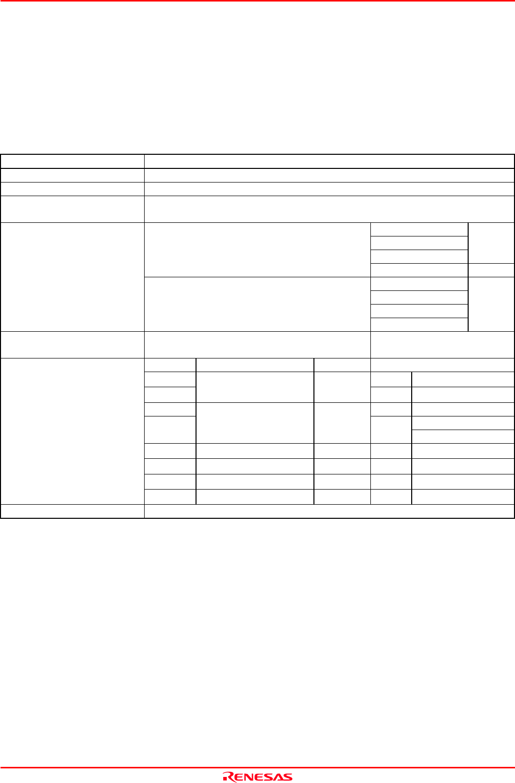
Table 4.1 Specifications of target MCUs for the M34571T2-CPE
Item Description
Applicable MCU 4500 Series 4571 Group
Evaluation MCU
M34571GDFP (mounted in the socket of the emulator)
Applicable power supply 3.0 V ±5 % or 5.0 V ±5 %
- Available only from the emulator, not from the user system
Divided-by 8-mode
Divided-by 4-mode
Divided-by 2-mode
6.0 MHz
3.0 V
Set the MCU power supply voltage selection switch
to 3V.
Through mode 4.4 MHz
Divided-by 8-mode
Divided-by 4-mode
Divided-by 2-mode
Maximum operating frequency
5.0 V
Set the MCU power supply voltage selection switch
to 5V.
Through mode
6.0 MHz
Clock supply Main clock (X
IN
)
Clock mounted on emulator
(6MHz: preinstalled, replacable)
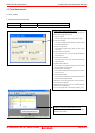
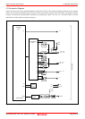
Pin Output type Direction Device
P00--P03 Input 74HC4050
P10--P13
N-channel open drain I/O
Output 74ALS641A
P30, P31 Input 74HC4050
74ALS641A(Nch)
D0--D3
N-channel open drain or
C-MOS output
I/O
Output
74VHC126(C-MOS)
P20, P21 N-channel open drain
I/O I/O
74HC4066
C C-MOS output
Output Output
74VHC08
K -
Input Input 74HC4066
Port emulation
RESET# -
Input Input
74VHC14
Connection to the user system Connected by 2.54-mm-pitch 26-pin flat cable