


M34571T2-CPE User’s Manual 2. Setup
REJ10J0972-0100 Rev.1.00 February 10, 2006 Page 24 of 72
2.5 Turning ON the Power
2.5.1 MCU Power Supply Voltage Selection Switch
Set the MCU power supply source selection switch of the emulator according to conditions of use.
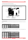
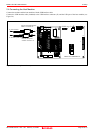
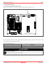
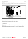
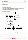
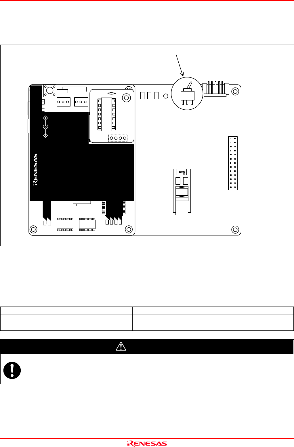
Figure 2.5 Jumper switch locations of the emulator
These are the jumper switches to select power supply to the MCU and its power voltage. As shown in Table 2.2 below, set the
switch according to the connection to the user system.
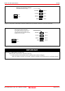
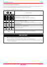
Table 2.2 Setting jumper switches
MCU power supply voltage selection switch (SW1) Description
3V Supplied from the emulator. The MCU operating voltage is 3.0 V.
5V Supplied from the emulator. The MCU operating voltage is 5.0 V.
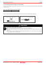
CAUTION
Note on Jumper Switch Settings:
Always shut OFF the emulator before changing the setting of the jumper switches, and connecting the cable.
Otherwise the internal circuit may cause a break.
MCU power supply voltage selection switch
M34571T2-CPEB REV.A
TP1
VDD2
GND
TP2
WRST
POF
LED1
POWER
SAFE
STATUS
J4
3V
5VSW 1
J3
13
14
1
26
MADE
POWER
COMPACT EMULATOR
INT
JP1
5.0V
JP2
3.3V
EXT
CLOCK
RESET
RUN
LED3
LED6
LED5LED4
POWER
SAFE
LED2
LED1
SAFE
POWER
POWER
CLOCK
RESET
RUN
M34571T2-CPE
STATUS
SYSTEM
STATUS
TARGET
MADE IN JAPAN
COMPACT EMULATOR
POWER
5.0V
USB
3V
5VSW 1