


15
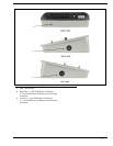
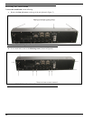
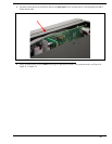
3. Carefully lift the chassis up and back to remove the back panel. Note, the back panel is still attached by the DB-9
Frame ribbon cable.
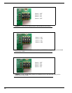
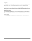
4. Using a pointed object, set the switches to the type of operation you desire. For operation modes, see Figure 10,
Figure 11, or Figure 12.
FIGURE 9. KP 32 CLD Inside Switch Bank