


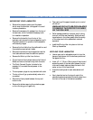
4
WORKSPACE / ELECTRICAL REQUIREMENTS
• Keep the area around your laminator clear with
adequate space around it so you can feed, receive
and trim mounted and/or laminated images.
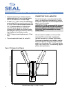
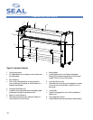
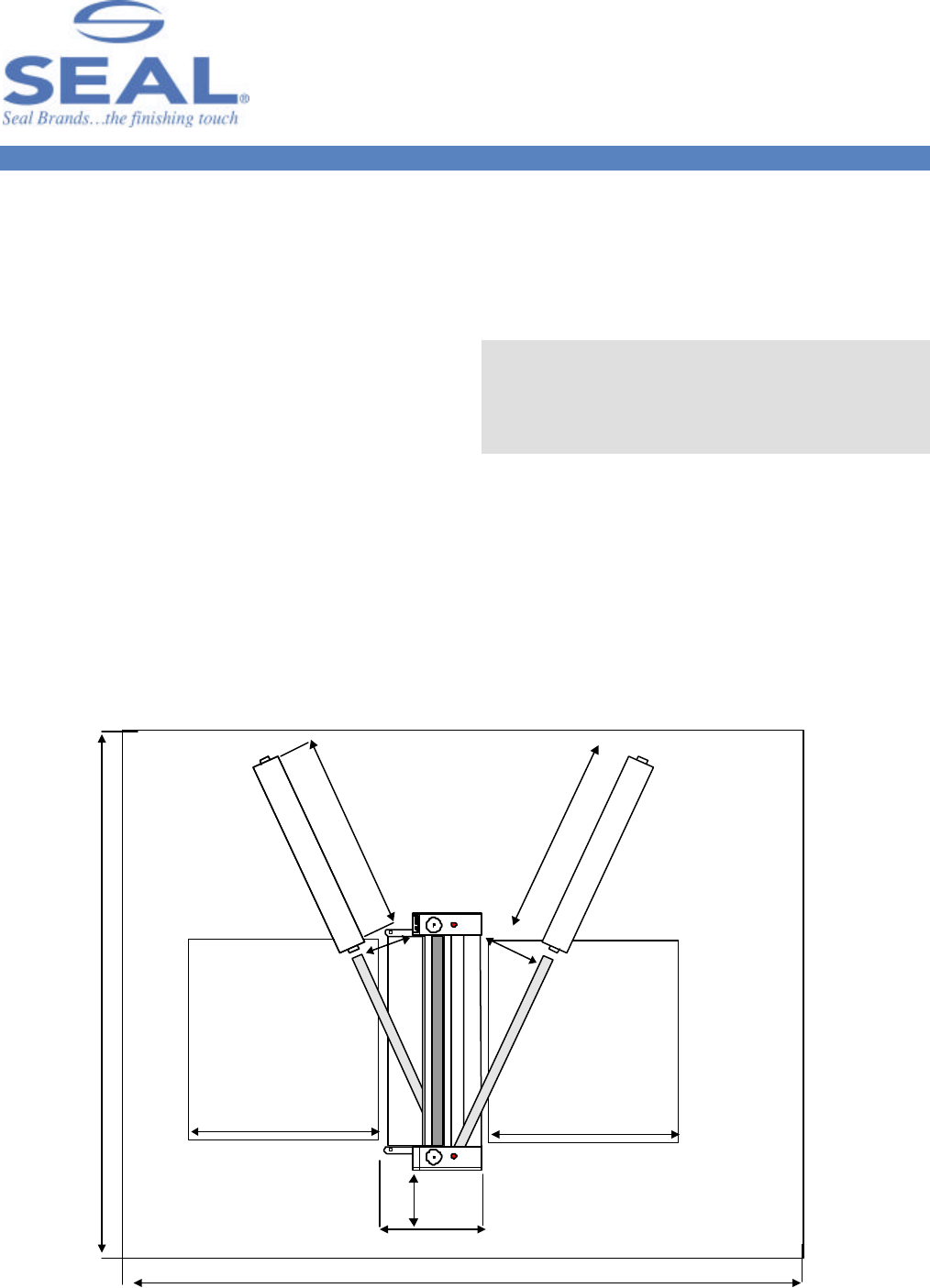
• An area 15’ x 11’ (4.5m x 3.4m) is the smallest area
recommended. We recommend a room size of 20’x
18’ (6.1m x 5.49m) to accommodate a laminator and
2 (4’ x 8’) tables on castors for finishing/layout
work. This area is required for loading and
unloading rolls of material onto the unwind shafts
and feeding and receiving the maximum mounting
board lengths into the laminator correctly.
• NOTE: Maximum board lengths are up to 12 feet
long.
• The work area should be level, flat, and well lit.
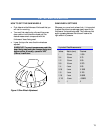
Figure 1. Workspace Area Diagram
CONNECTING YOUR LAMINATOR
Connect the laminator in accordance with the details
given on the identification plate attached to the rear of
the laminator. Refer also to the Technical Specifications
page for more information.
IMPORTANT! SEAL recommends that a licensed
electrician in accordance with electrical codes in
your area install your mains power or the warranty
will be void. Specifications subject to change
without notice.
We recommend the installation of a Ground Fault
Interrupter (GFI) circuit breaker if operating the
laminator near water or in an area of high humidity.
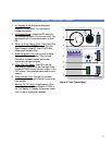
Once power is connected to your laminator, press the
Main Power Stand-by switch UP on the front control
panel to turn the laminator ON. If the Power Indicator
Light is not lit, refer to the “Troubleshooting” page for
problem solving information.
55"/140 cm
55"/140 cm
Maximum board length
Maximum board length
21/53 cm
(Door clearance)
"
Room Length = 2 x max. board length + 32" (81 cm)
32"/81 cm
Minimum Room Width =15 feet/4.5 meter
21"/53cm
Minimum Room Length = 11 feet / 3.4 meter
Rolls of Media
Rolls of Media
21"/53cm
Upper Rear Unwind Shaft
Front Lower Unwind Shaft