


Appendix B: Examples
B–2
Option 01 VXI Interface Module User Manual
This response indicates that the Power On bit of the Standard Event Status
register is set. This indicates that this is the first time an *ESR? query has
been sent to the Option 01 since power was applied to the module.
H Check the contents of the Standard Event Status register again.
WRITE *ESR?
READ 000
The content of the Standard Event Status register is equal to zero because
this register is read destructively. That is, it is set to zero after its contents are
reported following an *ESR? query.
H Enable VXI TTL trigger 1 to be pulsed low for 3 µsec after a channel is
closed on any of the relay modules.
WRITE output:ttltrg1:state on
H Check to see if VXI TTL trigger 1 is enabled.
WRITE output:ttltrg1:State?
READ 1
A response of 1 indicates that VXI TTL trigger 1 is enabled. A response of 0
indicates that this trigger is disabled.
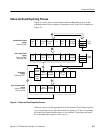
H Close channel 3 in section 5 of the VX4320 Module.
WRITE close (@m1(3!5))
H Configure the VX4330 as a 240-to-1 1-wire scanner.
WRITE route:conf:join m2,(1:6)
WRITE route:conf owire,m2,(1:6)
WRITE route:close:mode scan,m2,(1:6)
H Close channel 1 of section 1 of the VX4330.
WRITE route:close (@m2(1!1))
H Close channel 40 of section 2 of the VX4330.
WRITE route:close (@m2(40!2))
Note that channel 1 of section 1 will be opened before channel 40 of section
2 is closed because sections 1 and 2 have been joined and both sections have
been set to a close mode of “scan”.
H Close channels 1 through 10 on the VX4350 Module.
WRITE close (@m3(1:10))