


Command Descriptions
Option 01 VXI Interface Module User Manual
3–25
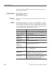
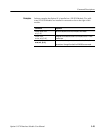
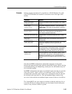
In these examples the Option 01 is installed on a VX4330 Module. Two addi-
tional VX4330 Modules are installed in consecutive slots to the right of this
module.
Command Response
route:configure
fwire,m1,(1:6)
Configure all six sections of the first VX4330 as 10-to-1 4-wire
scanners.
route:mode
scan,m1,(1:3)
Set the mode of operation of sections 1, 2, and 3 of the first
VX4330 to scan. In this mode, only one channel in a section is
closed at a time.
route:mode
mux,m1,(4:6)
Set the mode of operation of sections 4, 5 and 6 of the first
VX4330 to mux. In this mode one or more channels in a
section may be closed at the same time.
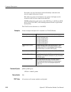
rout:conf owire,m3,(1) Configure section 1 of the third VX4330 as a 40-to-1 1-wire
scanner.
rout:conf
twire,m2,(2,3)
Configure sections 2 and 3 of the second VX4330 as 20-to-1
2-wire scanners.
route:configure
fwiri,m3,(1:6)
Configure all six sections of the third VX4330 as 10-to-1 4-wire
scanners with independent control of upper and lower
commons.
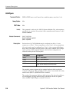
route:close (@m3(1!1)) Connect the lower half of channel 1, section 1, to the lower half
of the 4-wire common. In this example, section 1 is assumed to
be configured as a 10-to-1 4-wire scanner with independent
control of the upper and lower halves of the 4-wire common.
route:close
(@m3(20!1))
Connect the upper half of the 10th channel of section 1 to the
upper half of the 4-wire common. In this example, section 1 is
assumed to be configured as a 10-to-1 4-wire scanner with
independent control of the upper and lower halves of the 4-wire
common.
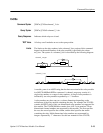
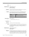
Note that in OWIRE configuration, unintended connections can be made
between the inputs that are paired with the selected MUX inputs. When selecting
even numbered relays for multiplexing, contact pairs for odd number relays are
also connected together.
In OWIRE configuration, the inputs are switched in pairs onto the two–wire bus
of the relay section. Input 1 (relay 1a_Lo) and input 2 (relay 1a_Hi) will be
switched at the same time, input 3 (relay 1b_Lo) and input 4 (relay 1b_Hi) will
be switched at the same time, etc. The odd numbered inputs connect to the
two–wire Lo bus and the even numbered inputs connect to the two–wire Hi bus.
The Scanner/MUX one–wire output is switched to either the odd relay (Lo) or
even relay (Hi) bus according to the last one–wire channel closed in the given
section, or any section to which it is joined.
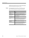
Examples