Operating Basics
2–4
Option 01 VXI Interface Module User Manual
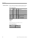
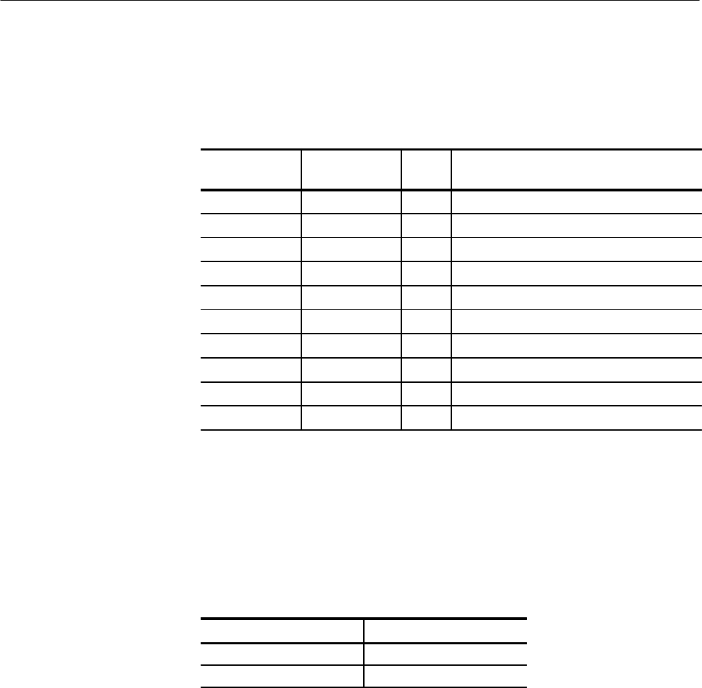
Table 2–1 contains a list of the Option 01 Configuration registers and a complete
description of each register. The offset is relative to the module base address.
Table 2–1: Register Definitions
Register
Address
(hexadecimal)
Type Value (Bits 15–0)
ID Register 0000 RO 1011 1111 1111 1101 (hexadecimal BFFD)
Device Type 0002 RO See Device Type definition below
Status 0004 R Defined by state of interface
Control 0004 W Defined by state of interface
Offset 0006 WO Not used
Protocol 0008 RO 1111 0111 1111 1111 (hexadecimal F7FF)
Response 000A RO Defined by state of the interface
Data High 000C Not used
Data Low 000E W Not fixed; command-dependent
Data Low 000E R Not fixed; command-dependent
RO is Read Only
WO is Write Only
R is Read
W is Write
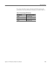
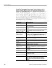
The Register Bit definitions are listed in Tables 2–2 and 2–3.
Table 2–2: Register Bit Definitions
Register Bit Definition
ID hexadecimal BFFD
Protocol hexadecimal F7FF
Configuration Registers


