


TMS380C26
NETWORK COMMPROCESSOR
SPWS010A–APRIL 1992–REVISED MARCH 1993
POST OFFICE BOX 1443 • HOUSTON, TEXAS
77251–1443
15
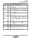
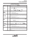
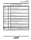
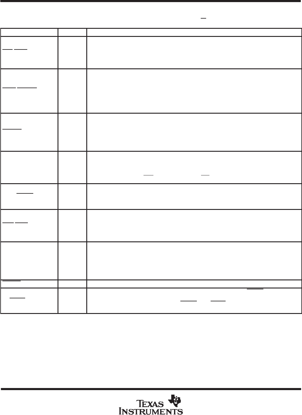
Terminal Functions (continued)
System Interface – Motorola Mode (SI/M
=L)
PIN NAME NO. I/O DESCRIPTION
SRD/SUDS 61 I/O
Upper Data Strobe (see Note 3). This pin serves as the active-low upper data strobe.
This pin is an input during DIO and an output during DMA.
H = Not valid data on SADH0-SADH7 lines.
L = Valid data on SADH0-SADH7 lines.
SRDY/SDTACK 60 I/O
System Data Transfer Acknowledge (see Note 3). The purpopse of this signal is to indicate to the bus
master that a data transfer is complete. This signal is internally synchronized to SBCLK. During DMA
cycles, it must be asserted before the falling edge of SBCLK in state T2 in order to prevent a wait state.
This signal is an output when the TMS380C26 is selected for DIO, and an input otherwise.
H = System bus NOT ready.
L = Data transfer is complete; system bus is ready.
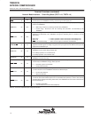
SRESET 25 IN
System Reset. This input is activated to place the adapter into a known initial state. Hardware reset
will put most of the TMS380C26 output pins into a high-impedance state and place all blocks into the
reset state.
H = No system reset.
L = System reset.
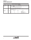
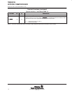
SRSX
SRS0
SRS1
28
27
26
IN
System Register Select. These inputs select the word or byte to be transferred during a system DIO
access. The most significant bit is SRSX and the least significant bit is SRS1 (see Note 1).
MSb
LSb
Register Selected = SRSX SRS0 SRS1
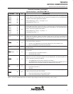
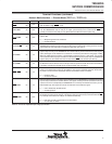
SRS2/SBERR 33 IN
Bus Error. Corresponds to the bus error signal of the 68000 microprocessor. It is internally
synchronized to SBCLK. This input is driven low during a DMA cycle to indicate to the TMS380C26
that the cycle must be terminated. See Section 3.4.5.3 of the
TMS380 Second-Generation Token
Ring User’s Guide
(SPWU005) for more information (see Note 1).
SWR/SLDS 40 I/O
Lower Data Strobe (see Note 3). This pin is an input during DIO and an output during DMA. This pin
serves as the active-low lower data strobe.
H = Not valid data on SADL0-SADL7 lines.
L = Valid data on SADL0-SADL7 lines.
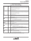
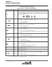
SXAL 42 OUT
System Extended Address Latch. This output provides the enable pulse used to externally latch the
most significant 16 bits of the 32-bit system address during DMA. SXAL is activated prior to the first
cycle of each block DMA transfer, and thereafter as necessary (whenever an increment of the DMA
address counter causes a carry-out of the lower 16-bits). Systems that implement parity on
addresses can use SXAL to externally latch the parity bits (available on SPL and SPH) for the DMA
address extension.
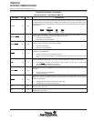
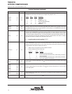
SYNCIN 108 IN Reserved. This signal must be left unconnected (see Note 1).
S8/SHALT 32 IN
System Halt/Bus Error Retry. If this signal is asserted along with bus errror (SBERR), the adapter will
retry the last DMA cycle. This is the re-run operation as defined in the 68000 specification. The
BERETRY counter is not decremented by SBERR
when SHALT is asserted. See Section 3.4.5.3 of
the
TMS380 Second-Generation Token Ring User’s Guide
(SPWU005) for more information.
NOTES: 1. Pin has an internal pullup device to maintain a high voltage level when left unconnected (no etch or loads).
3. Pin should be tied to V
CC
with a 4.7-kΩ pullup resistor.