


TMS380C26
NETWORK COMMPROCESSOR
SPWS010A–APRIL 1992–REVISED MARCH 1993
POST OFFICE BOX 1443 • HOUSTON, TEXAS
77251–1443
28
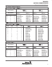
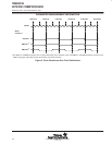
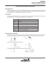
Bit 12: SINTEN — System-Interrupt Enable
This bit allows the host processor to enable or disable system interrupt requests from the
TMS380C26. The system interrupt request from the TMS380C26 is on the SINTR/SIRQ pin. The
following equation shows how the SINTR/SIRQ pin is driven. The table also explains the results
of the states.
SINTR/SIRQ = (PSDMAEN * SWHRQ * !SWHLDA) + (SINTEN * SYSTEM_INTERRUPT)
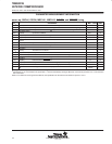
PSDMAEN SWHRQ SWHLDA SINTEN
SYSTEM
INTERRUPT
(SIFSTS Reg.)
RESULT
1
†
1 1 X X Pseudo-DMA is active.
1
†
1 0 X X
The TMS380C26 generated a system
interrupt for a pseudo-DMA.
1
†
0 0 X X Not a pseudo-DMA interrupt.
X X X 1 1
The TMS380C26 will generate a system
interrupt.
0 X X 1 0
The TMS380C26 will not generate a system
interrupt.
0 X X 0 X
The TMS380C26 can not generate a system
interrupt.
†
The value on the SHLDA/SBGR pin is ignored.
Bit 13: PEN — Adapter Parity Enable
This bit determines whether data transfers within the TMS380C26 are checked for parity.
0 = Data transfers are not checked for parity
1 = Data transfers are checked for correct odd parity.
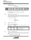
Bit 14 — 15: NSELOUT (0–1) — Network selection outputs.
The values in these bits control the output pins NSELOUT0 and NSELOUT1. These bits can only
be modified while the ARESET bit is set.
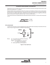
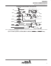
These bits can be used to software configure a multi-protocol TMS380C26, as follows:
The NSELOUT0 and NSELOUT1 pins should be connected to TEST0 and TEST1 pins
respectively (TEST2 should be left unconnected or tied high). NSELOUT0 should be used to
select network speed and NSELOUT1 network type, as shown in the table below:
NSELOUT0 NSELOUT1
0 0 Reserved
0 1 16 Mbps token ring
1 0 Ethernet (802.3/Blue Book)
1 1 4 Mbps token ring
At power-up these bits are set NSELOUT1 = 1, NSELOUT0 = 0 corresponding to 16 Mbps token
ring.