


TMS380C26
NETWORK COMMPROCESSOR
SPWS010A–APRIL 1992–REVISED MARCH 1993
POST OFFICE BOX 1443 • HOUSTON, TEXAS
77251–1443
21
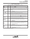
On every cycle the system interface compares all the system clocks to a reference clock. If any of the clocks
become invalid, the TMS380C26 enters the slow clock mode, which prevents latchup of the TMS380C26. If the
SBCLK is invalid, any DMA cycle is terminated immediately; otherwise, the DMA cycle is completed and then
the TMS380C26 is placed in slow clock mode.
When the TMS380C26 enters the slow clock mode, the clock that failed is replaced by a slow free-running clock
and the device is placed into a low-power reset state. When the failed clock(s) return to valid operation, the
TMS380C26 must be re-initialized.
Using DMA, a continuous transfer rate of 64 Mbits per second (Mbps), which is 8 MBytes per second (MBps),
can be obtained. For pseudo-DMA a continuous transfer rate of 48 Mbps (6 MBps) can be obtained when using
a 16-MHz clock. The DIO transfer rate is not a significant issue, since the main purpose of DIO is for downloading
and initialization. For comparison, the ISA bus continuous DMA transfer is rated for approximately 23 Mbps.
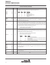
memory interface (MIF)
The Memory Interface (MIF) performs the memory management to allow the TMS380C26 to address 2 MBytes
in local memory. Hardware in the MIF allows the TMS380C26 to be directly connected to DRAMs without
additional circuitry. This glueless DRAM connection includes the DRAM refresh controller.
The MIF also handles all internal bus arbitration between these blocks. When required, the MIF then arbitrates
for the external bus.
The MIF is responsible for the memory mapping of the CPU of a task. The memory map of DRAMs, EPROMs,
Burned-in Addresses (BIA), and External Devices are appropriately addressed when required by the System
Interface (SIF), Protocol Handler (PH), or for a DMA transfer.
The memory interface is capable of a 64 Mbps continuous transfer rate when using a 4-MHz local bus (64-MHz
device crystal).
protocol handler (PH)
The Protocol Handler (PH) performs the hardware-based realtime protocol functions for a token ring or Ethernet
Local Area Network (LAN). Network type is determined by the test pins TEST0–2. Token ring network is
determined by software and can be either 16-Mbps or 4-Mbps. These speeds are not fixed by the hardware,
but by the software.
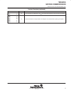
The (PH) converts the parallel transmit data to serial network data of the appropriate coding, and converts the
received serial data to parallel data. The PH data management state machines direct the transmission/reception
of data to/from local memory through the MIF. The PH’s buffer management state machines automatically
oversee this process, directly sending/receiving linked-lists of frames without CPU intervention.