


Machine Configuration August, 2006
Spec-22
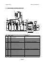
No. Component Function
PCBs
PCB1 PFC (Paper Feed Control) Controls paper feed.
PCB2 AC Drive Board
Controls the power supply to the fusing lamps,
heaters, and PSU.
PCB3 PSU (Power Supply Unit)
Supplies DC current to the machine and contains
the AC drive that controls the fusing lamp power
supply.
PCB4 DRB (Drive Board)
Contains the circuits for the stepping motors that
drive the printer engine, and distributes electrical
power to all other PCBs.
PCB5 IOB (Input/Output Board)
The I/O control board controls 1) Input and output
ports for all sensors, motors, solenoids of the
engine, 2) drivers, 3) high voltage power supply
for PWM, and 4) analog input signals.
PCB6
Power Pack: Development
Bias
Supplies the voltage for the bias applied to the
developer in the PCUs by the development rollers.
PCB7 Power Pack: Charge
Supplies the voltage for the charge applied to the
OPC drums by the charge roller.
PCB8 Power Pack: Transfer
Supplies charge to 1) the four image transfer
rollers that pull the toner images from the four
from the four drums (Y, M, C, K), and 2) to the
paper transfer roller that pulls the image off the
ITB onto paper.
PCB9 Power Pack - Separation Supplies the dc/ac charges for paper separation.
PCB10 DMB (Drum Motor Board) Controls the motors that drive the OPC drums.
PCB11 TMB (Transfer Motor Board) Controls the motor that drives the ITB.
PCB12 Potential Sensor Board
Processes data from the Y, M, C, K, potential
sensors.
PCB13 PPB (Peltier Board) Controls the operation of the Peltier unit.
PCB14 CNB (Connector Board) Sorts and routes signals to electrical components.
PCB15 IDCB - C1
One of two ID control boards at the base of the
Cyan STC. The CPU reads the board to confirm
that the correct STC is inserted into the correct
bin.
PCB16 IDCB - M1
One of two ID control boards at the base of the
Magenta STC. The CPU reads the board to
confirm that the correct STC is inserted into the
correct bin.
PCB17 IDCB - K1
One of two ID control boards at the base of the
Black STC. The CPU reads the board to confirm
that the correct STC is inserted into the correct
bin.
PCB18 IDCB - Y1
One of two ID control boards at the base of the
Yellow STC. The CPU reads the board to confirm
that the correct STC is inserted into the correct
bin.
PCB19 SBU (Sensor Board Unit)
Contains the CCD. Converts CCD analog signals
to digital signals.
PCB20
SIOB (Scanner Interface
Board)
Controls all the sensors in the scanner unit and
controls the carriage drive stepping motors.
PCB21 Lamp Regulator
Converts the ac power input to a stable, high
frequency ac output to the exposure lamp.