


August, 2006 IMAGE PROCESSING
6-41
Detailed
Descriptions
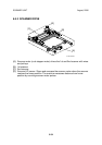
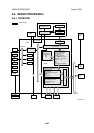
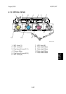
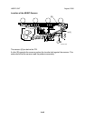
6.6.2 SBU (SENSOR BOARD UNIT)
SBU
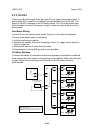
The VPU (Video Processor Unit) does the following functions:
• Black level correction
• White level correction
• Gradation calibration
• ADS control (Background Density) (*ADS: Auto image Density Selection)
• Creating the SBU test pattern
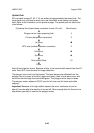
Operation Summary
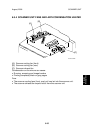
The signals from the 3-line CCD, one line for each color (R, G, B) and 2 analog
signals per line (ODD, EVEN), are sampled by the ASIC and converted to digital
signals in the 10-bit A/D converter. This is the first phase of processing the data
scanned from the original.
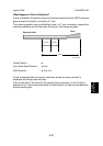
Storing Operation Settings
The controller stores the SBU settings. These values must be restored after the
lens block is replaced:
SP4008 001 Sub Scan Mag Sub Scan Magnification Adjustment
SP4010 001 Sub Scan Reg Sub Scan Registration Adjustment
SP4011 001 Main Scan Reg Main Scan Registration Adjustment
Also, before lens block replacement, enter the SP mode and note the settings of
SP4800 001 to 003 (ARDF density adjustments for R, G, B). After lens block
replacement, do some copy samples with the ARDF, then check the copies. If the
copies have background, change SP4800 001 to 003 to their previous settings, or
adjust until the background is acceptable. These SP codes are also used to adjust
the ARDF scanning density, if the scanning densities of the ARDF and the platen
mode are not the same.
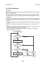
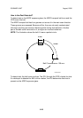
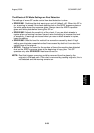
SBU Test Mode
There are two SP codes to create a test pattern which can be used as a diagnostic
tool to troubleshoot problems in the SBU:
• SP4907 001 SBU Pattern - Test Pattern
• SP4907 002 SBU Pattern - Select Fixed Pattern
To print the pattern:
• Select the pattern to print.
• Touch "Copy Window" then press the Start key twice.