


8 G9000 Installation and Operation Manual
1.4 OPERATION OVERVIEW
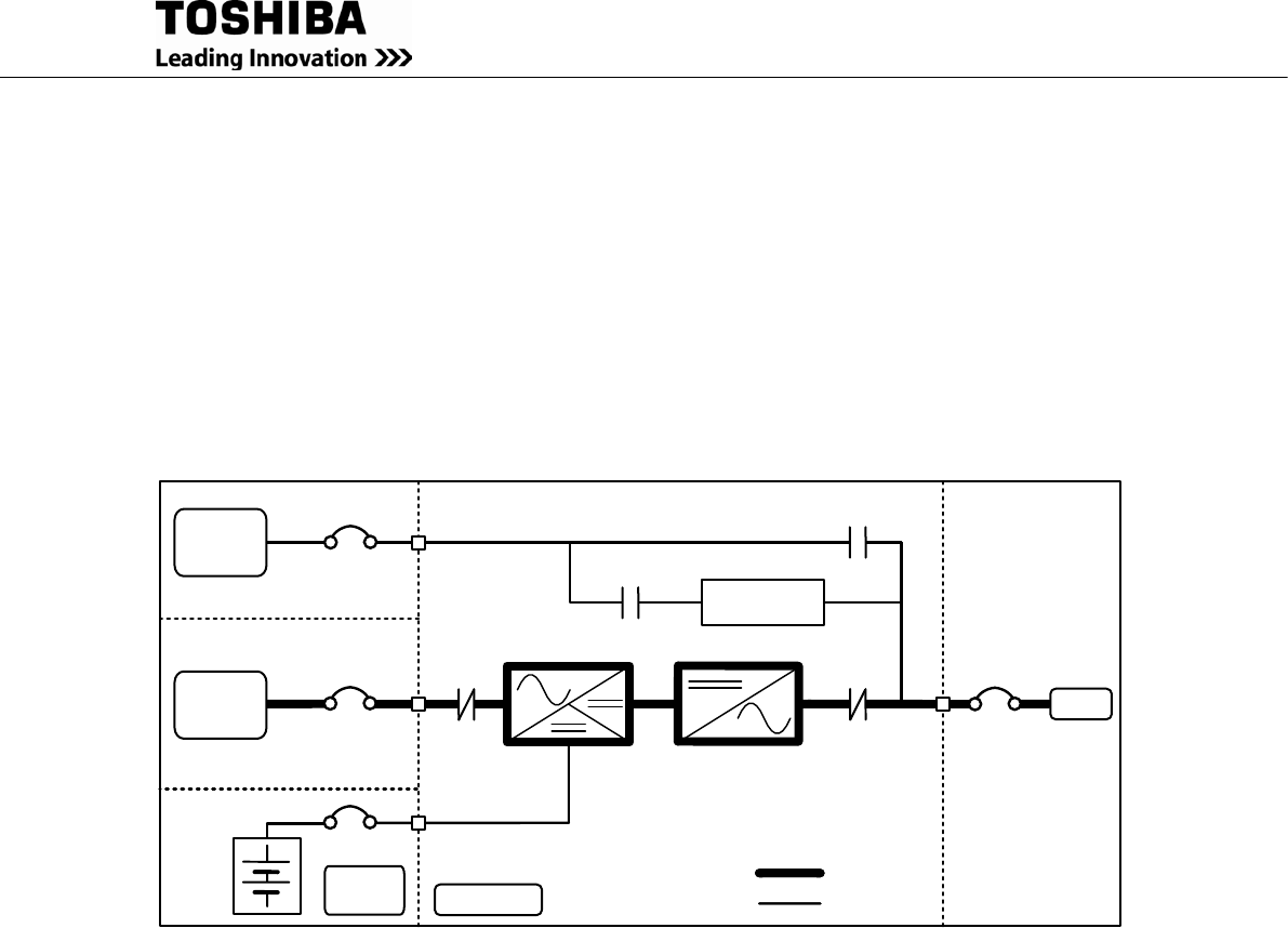
The UPS provides two power paths between the utility source and the critical load.
Figure 1.1 shows the path for normal operation, with the load powered by the inverter.
Figure 1.2 shows the path for bypass operation, with the load supplied through the static bypass
line.
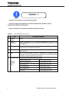
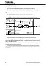
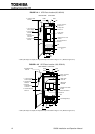
A) Normal operation: Load power supplied by each system UPS inverter.
FIGURE 1.1 Single Line Diagram – Normal Operation: Load powered by UPS inverter
Bypass
Input
CB
User supplied
MCCB
Static Transfer
Switch
52S
AC
Input
CB1
CONVERTER
INVERTER
52C
Output
Power Flow
Not in Use
UPS Module
Battery
Cabinet
CB
User supplied
MCCB
CB2
External
Battery
CB3
CB
CHARGER
During normal operation, the path through the UPS inverter is used to power the load.
In Figure 1.1 input AC power is converted to DC by the Converter. DC power is utilized to charge
the UPS battery and to provide power to the Inverter. The Inverter converts the DC power to clean AC
power to supply the critical load.
The conversion - inversion process eliminates any voltage transients or fluctuations existing in the
input power before it reaches the critical load.
The power drawn by the critical load is equally shared between all UPS systems when multiple
UPSs are in Parallel Operation. (Refer to Figure 3.6 that shows a sample of Parallel Operation System
Configuration.)