


G9000 Installation and Operation Manual 43
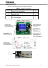
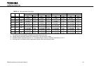
The parts (included RemotEyeII) for UPS monitoring are listed below.
TABLE 2-1 Parts list for UPS monitoring
Parts No.
Part name
Qt’y
1 PSAU-60* :Power supply PCB (PS1) 1
2 3BBA0083P001 :Cable1 1
3 RemotEyeII module 1
4
D-sub 9-pin to RJ45 Cable:Cable2
1
5 12V Power Cable:Cable3 1
* – PCB revision suffix may be applied.
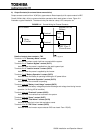
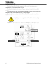
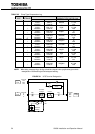
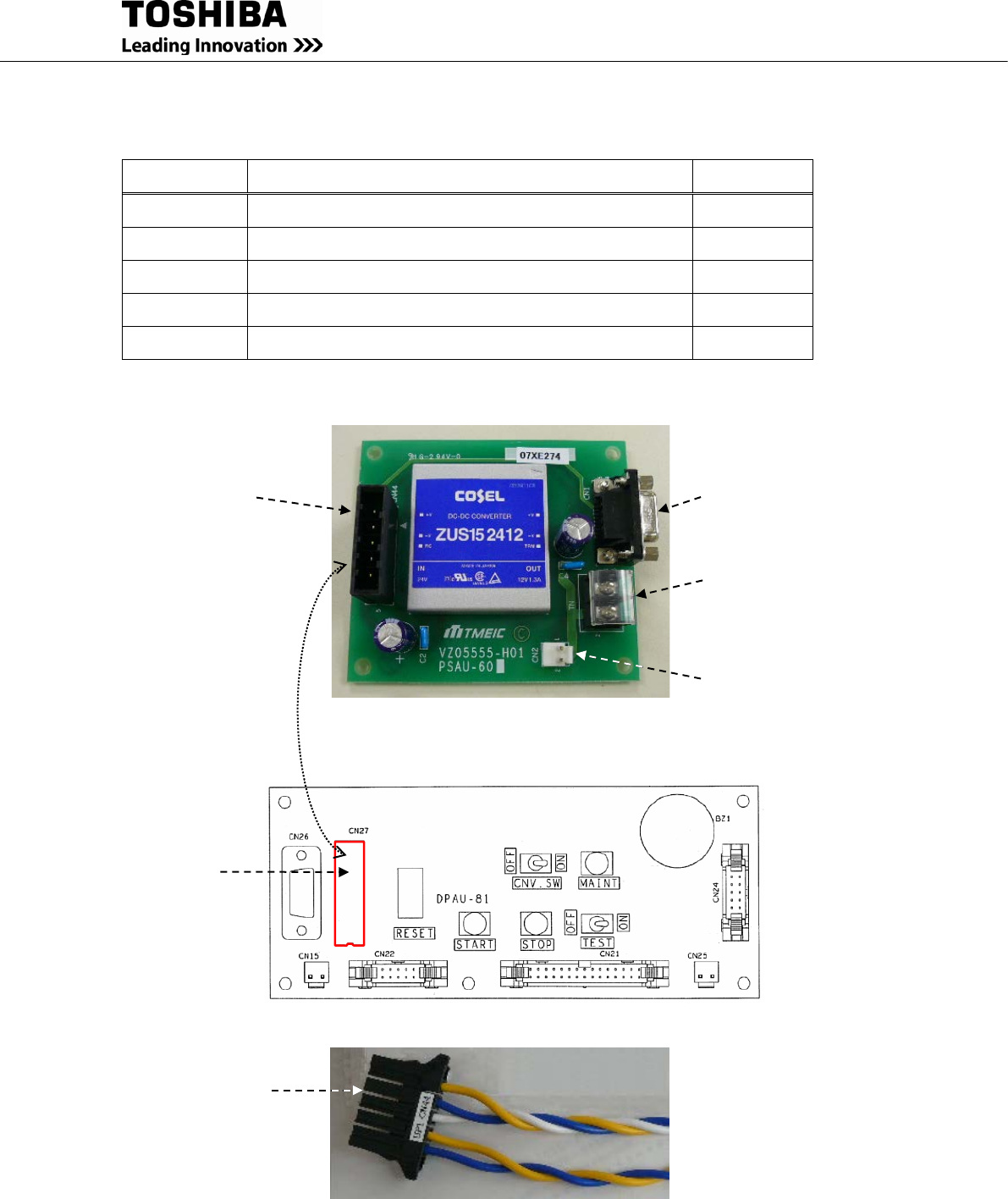
Connected with
3BBA0083P001(Cable1)
Shown in FIGURE 2.17.
D-sub connector CN1
to be connected with
RemotEyeII.
Terminal block TN
to feed 12VDC power
to RemotEyeII.
(12V across P to N)
Optional interface CN2
to give 12VDC power
(12V Pin#1 to #2)
(Note 12VDC exposed)
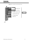
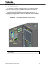
FIGURE 2.15 PSAU-60 PCB (PS1)
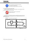
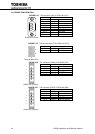
FIGURE 2.17 3BBA0083P001 (Cable1)
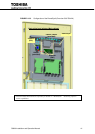
Connector CN44
to be connected with
CN27 of DPAU-81(SW1).
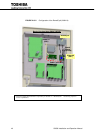
FIGURE 2.16 DPAU-81 (SW1)
Connector CN27
to be connected with
CN44 of PSAU-60(PS1).
D3200 5pin
(housing)