62 G9000 Installation and Operation Manual
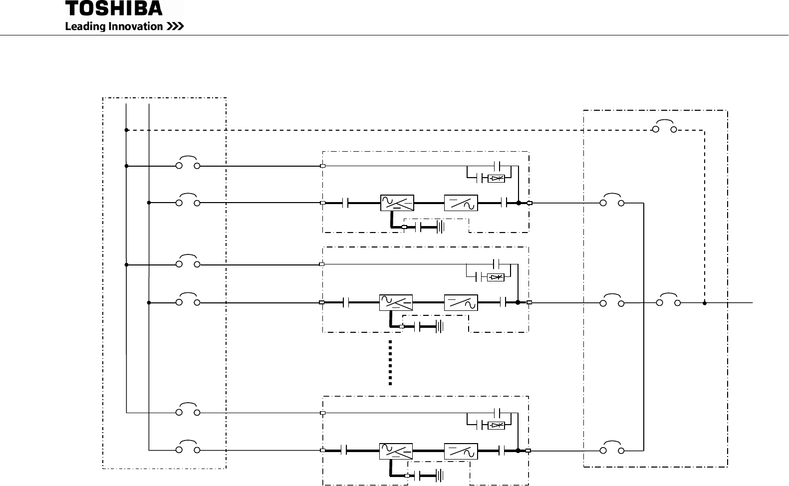
FIGURE 3.6 Diagram of Power Wire Connections (Parallel System Configuration)
52L1
UPS
Breaker
52L2
UPS
Breaker
Toshiba Tie Cabinet (TTC)
UPS
Breaker
52Ln (*1)
52MB
Maintenance
Bypass Breaker
Output
Breaker
52CS
Bypass input
AC input
Bypass input
AC input
Bypass input
AC input
AC output
AC output
AC output
Bypass
CB2
Inverter
CB1
UPS-1
Battery
52C
Converter
/Charger
52S
Bypass
CB2
Inverter
CB1
UPS-2
Battery
52C
Converter
/Charger
52S
Bypass
CB2
Inverter
CB1
UPS-n
Battery
52C
Converter
/Charger
52S
(*1) n: Maximum=4 (80-225kVA)
Maximum=8 (300-750kVA)


