


G9000 Installation and Operation Manual 47
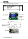
After the completion of the input power cables connection:
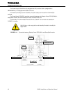
With a phase rotation meter, check that the phase rotation of the AC Input power
terminals A, B and C as well as the Bypass Input power terminals A40, B40 and C40
are correct. The proper phase rotation is clockwise A(R)
→
B(S)
→
C(T).
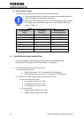
3. Connect the grounding conductor from the input service
entrance to the UPS Ground Bar (E).
4. Two (2) sources feeding the UPS:
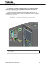
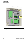
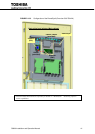
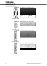
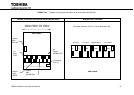
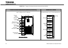
(1) Connect the AC input power cables from the input service entrance to the AC input power
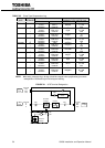
terminals, identified as A, B, C in Figures 3.1 and 3.2.1 – 4. Input cables must be sized
for an ampere rating larger than the maximum input drawn by the converter. (Refer to
equipment nameplate for current ratings.) Confirm that an external bypass input circuit
breaker (MCCB) is installed (refer to WARNING 4, page 5). Connect the bypass input
power cables from the input service entrance to the bypass input power terminals,
identified as A40, B40 and C40 in Figures 3.1 and 3.2.1 – 4. Bypass input cables must be
sized for an ampere rating larger than the maximum output current capacity of the UPS.
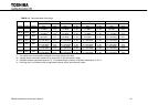
Refer to Table 3.4 for recommended cable sizes.
(2) Connect the external signal terminal block as desired. Refer to Section 2.4 and Figure
2.10 for functional description. 14 AWG (2mm
2
), or less, shielded conductor is
recommended.
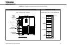
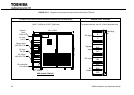
5. One (1) source feeding the UPS:
(1) Confirm that an external input circuit breaker sized to protect both the AC input and the
bypass line is installed. (Refer to equipment nameplate for current ratings.) Connect the
bypass input power cables from the input service entrance to the bypass input power
terminals, identified as A40, B40 and C40 in Figures 3.1 and 3.2.1 – 4. Input cables must
be sized for an ampere rating larger than the maximum current capacity of the UPS.
Refer to Table 3.4 for recommended cable sizes.
(2) Using adequately sized conductors and referring to the appropriate figure identified in
Figures 3.1 and 3.2.1 – 4, connect jumper bypass terminals A40, B40, C40 to AC input
power terminals A, B, C as identified in Figures 3.1 and 3.2.1 – 4.
!
NOTE
REQUIRED