


G9000 Installation and Operation Manual 9
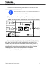
In the event of a UPS module failure during Parallel Operation, the critical load power will be
continually supplied and shared by all other UPS.
The Bypass Input breaker and cables are to be supplied and installed by the user or
the constructor. (See WARNING 4 on page 5)
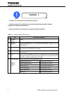
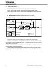
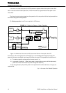
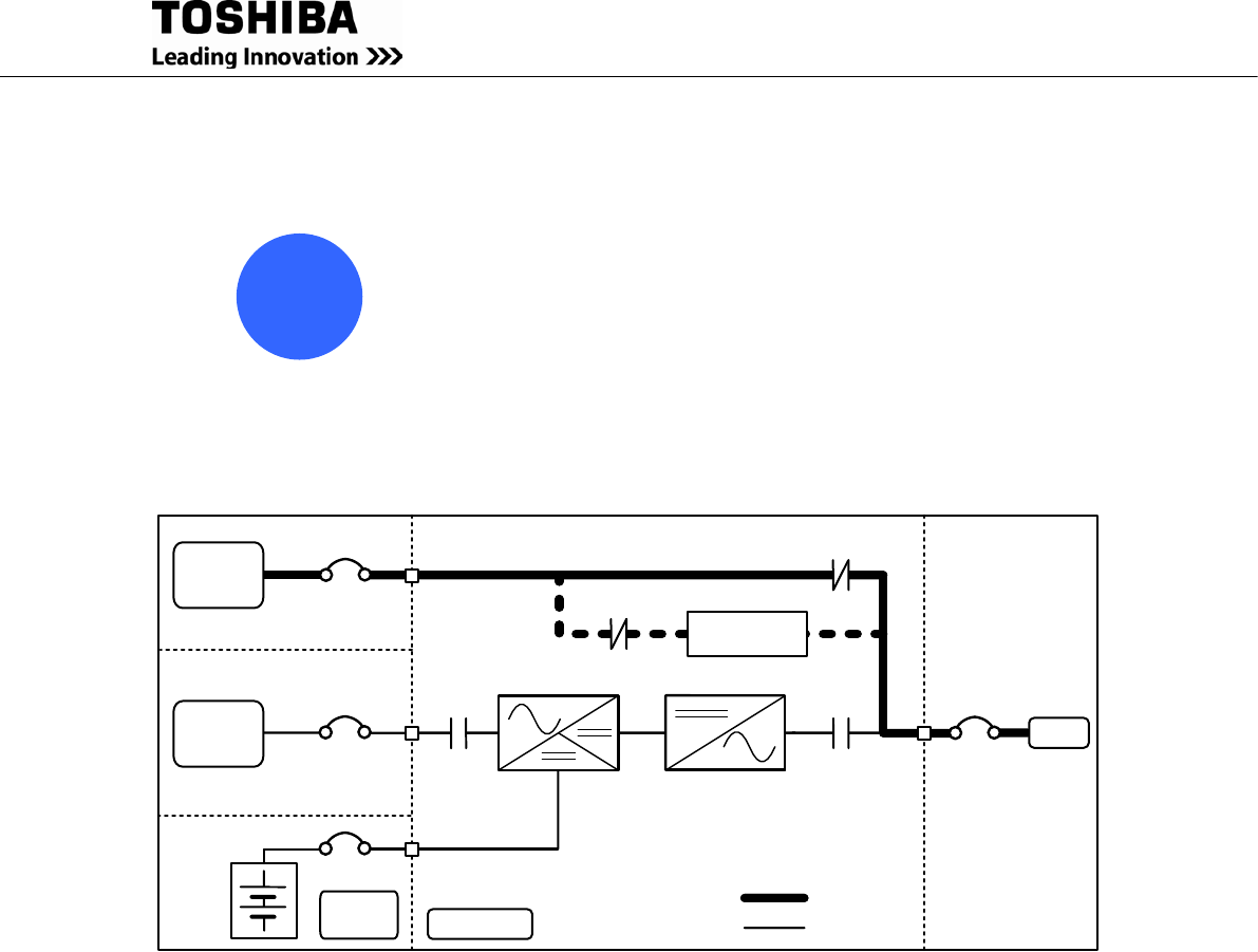
B) Bypass Operation: Load Power supplied through UPS internal static bypass line.
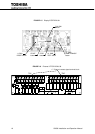
FIGURE 1.2 Single Line Diagram – Bypass Operation: Load fed through static bypass line.
Bypass
Input
CB
User supplied
MCCB
52S
AC
Input
CB1
CONVERTER
INVERTER
52C
Output
Power Flow
Not in Use
UPS Module
Battery
Cabinet
CB
User supplied
MCCB
CB2
External
Battery
CB3
CB
Static Transfer
Switch
CHARGER
Figure 1.2 shows the Internal Bypass line is a Hard-wired line through 52S which supplies the
critical load with unconditioned bypass input power. Upon switching to the Internal Bypass line, the
Static Transfer Switch line through CB3 (herein after STS contactor CB3) supplies the power
immediately, and then the Internal Bypass line through 52S supplies the power. In the event of a
switching to the Bypass line, the power to the critical load will be uninterrupted. The purpose of this
Internal Bypass line is to route power to the critical load while the UPS module is de-energized
(converter and inverter), and during Start-up before the system is fully operational.
Each UPS internal static bypass line will equally share the power supplied to the critical load
whenever the system is in the Parallel Operation.
!
NOTE