


G9000 Installation and Operation Manual 63
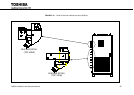
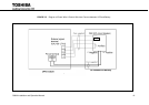
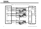
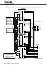
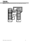
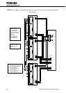
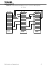
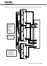
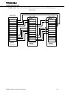
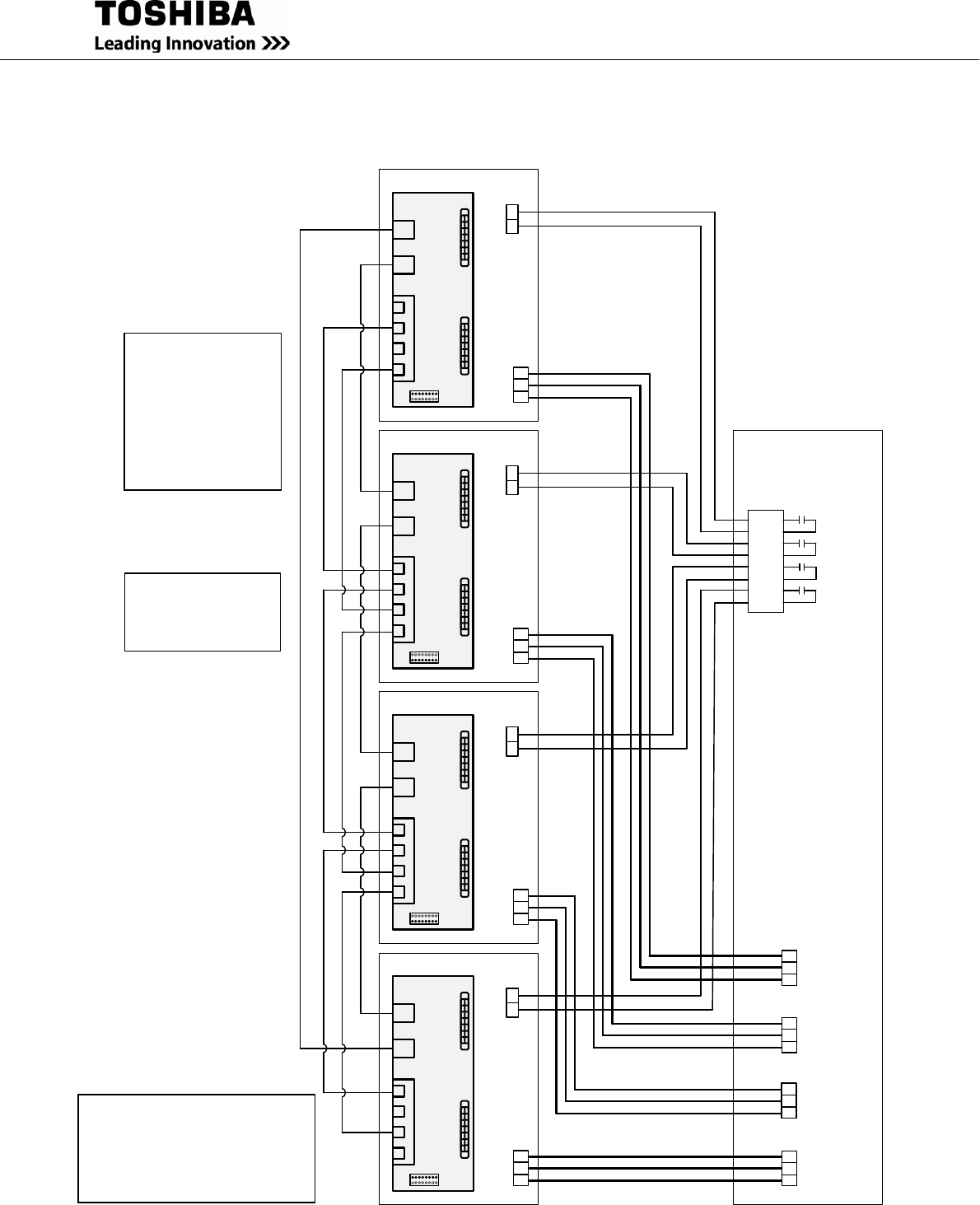
FIGURE 3.7.1 Diagram of Power Wire & Control Wire Connections for 4 units in MMS Configuration
(80-225kVA)
IFAU-08
CN
96
CN95
CN94
TLIN
ON
CBIN
CBOUT
CAOUT
CAIN
TLOUT
TN1
IOAU
-09
5
6
AC
OUTPUT
UPS-
1
IFAU-08
CN96
CN
95
CN94
TLIN
OFF
CBIN
CBOUT
CAOUT
CAIN
TLOUT
TN1
IOAU-09
5
6
AC
OUTPUT
UPS-2
IFAU
-08
CN96
CN95
CN94
TLIN
OFF
CBIN
CBOUT
CAOUT
CAIN
TLOUT
TN1
IOAU-09
5
6
AC
OUTPUT
UPS-3
IFAU-08
CN96
CN95
CN94
TLIN
ON
CBIN
CBOUT
CAOUT
CAIN
TLOUT
TN1
IOAU-
09
5
6
AC
OUTPUT
UPS-4
A
B
C
UPS-1
A
B
C
UPS
-2
A
B
C
UPS-3
AC OUTPUT
43
44
45
46
47
48
49
50
52L1-
AX
52L
2-AX
52
L4-AX
A
B
C
UPS-4
52L3-
AX
A50
B50
C50
A50
B50
C50
A
50
B
50
C50
A50
B50
C50
*
1
*2
*2
*2
*2
Toshiba Tie Cabinet (TTC)
Use Ethernet STP
(Shielded Twisted
Pair) Cable (Cat 5 or
Cat 6) with RJ45
modular connectors
for all communication
cabling.
Use of UTP
(Unshielded Twisted
Pair) Cable may
Total cable length
from UPS-1 to UPS-n
should be within
100m.
*1 Return from the last
UPS module to the first UPS
module (continuous loop).
*2 DIP switch position
UPS-1 and UPS-n (n=2-4): ON
Otherwise : OFF