


G9000 Installation and Operation Manual 53
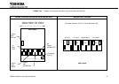
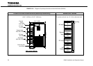
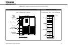
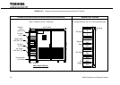
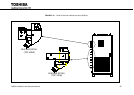
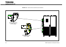
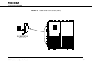
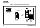
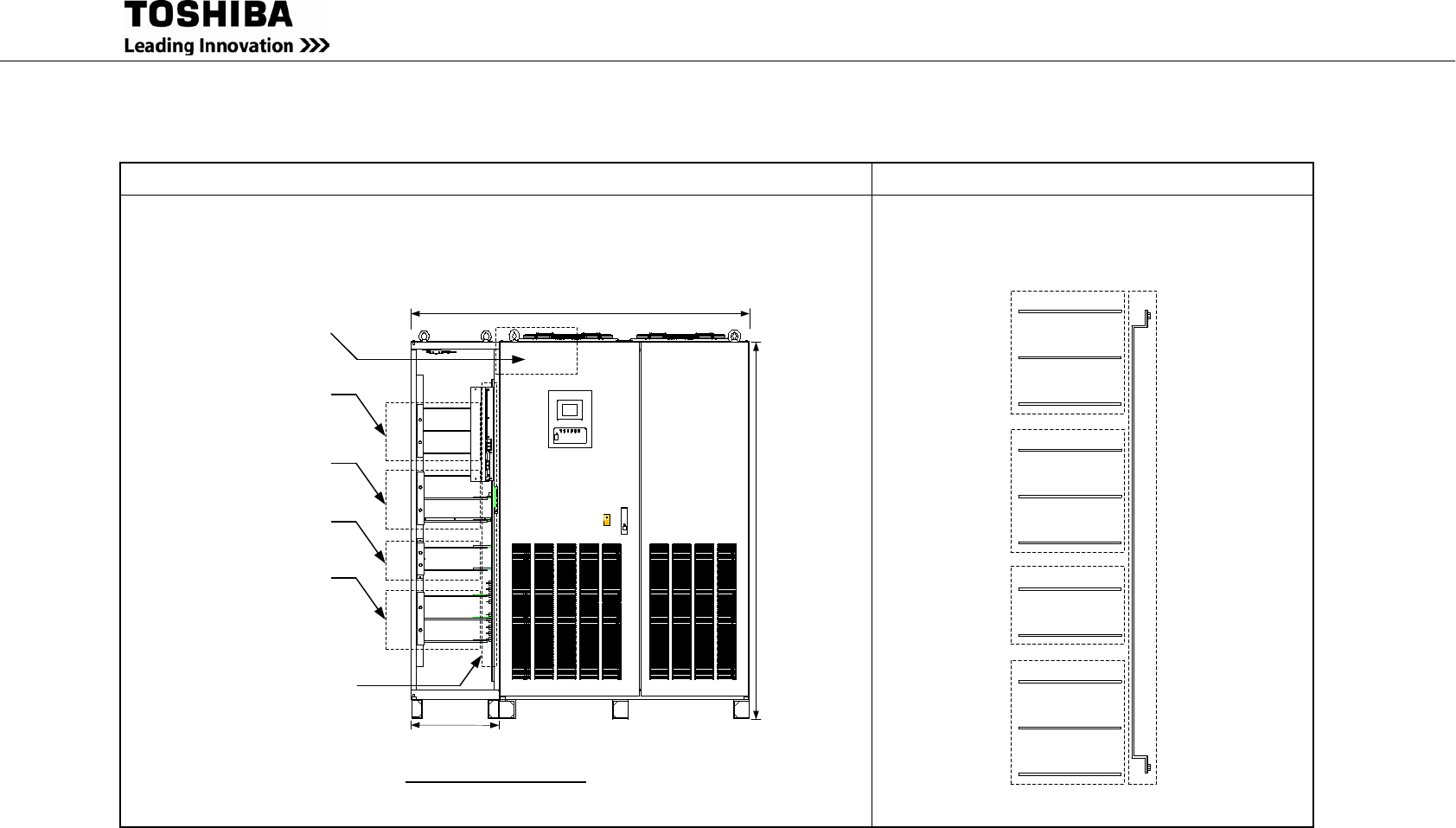
FIGURE 3.2.3. Diagram of input/output bus bars and terminal blocks (500kVA)
Location of bus bars and terminal blocks (Bottom/Top/Left Side Entry) Detailed Power Terminals
H=80.7” (2050mm) D=32.7” (830.6mm)
18.5" (470)
AC Input
A, B, C
Bypass Input
A40, B40, C40
DC Input
BP, BN
AC Output
A50, B50, C50
Grounding Bar
(not shown)
78.7" (2000)
70.9" (1800)
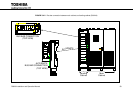
External
Block
IOAU-09
UPS module (500kVA)
For power terminals, use 1/2” (12mm) diameter bolts.
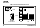
AC Input
A
B
C
Bypass
Input
A40
B40
C40
BP
BN
DC Input
AC
Output
A50
B50
C50
Grounding
Bar
E