


G9000 Installation and Operation Manual 45
3 INSTALLATION AND OPERATION
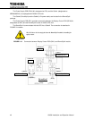
3.1 TRANSPORTATION AND INSTALLATION
TABLE 3.1 How to transport and install the system
Transportation Installation
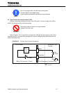
Transport unit with forklift.
If carry by overhead crane, use four M12
eyebolts. (Not provided)
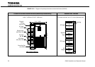
Using the pre-drilled four holes in the UPS
channel base, anchor the unit using
appropriate hardware. (Not provided)
Do not transport UPS cabinet laid horizontally.
Cabinets must be maintained upright within ± 15° of the vertical
during handling.
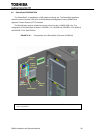
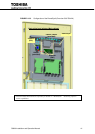
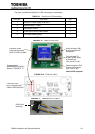
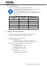
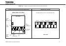
3.2 INSTALLATION PROCEDURE
A) Note the load tolerance of the floor
Refer to Table 3.2 for list of UPS weights.
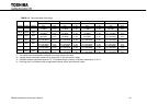
TABLE 3.2 List of UPS weights
UPS Capacity (kVA) 80 100 160 225 300 500 750
Weight (lbs)
855
855
1160
1230
2260
3360
4250
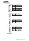
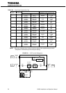
B) Minimum clearance required for ventilation
Right side 1 in. (25 mm) (not required when sidecars are used)
Left side 1 in. (25 mm) (not required when sidecars are used)
Back side 0.0 inch (0 mm)
Top side (80-225kVA) 20 inches (500 mm) (for air flow)
Top side (300-750kVA) 23.6 inches (600 mm) (for air flow)
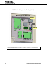
C) Space requirement for routine maintenance
Allow for the following space at the time of installation.
Front (80-225kVA) 40 inches (1000 mm)
Front (300-750kVA) 42.3 inches (1075 mm)
Sides 0.0 inch (0 mm)
Back side 0.0 inch (0 mm)
Top side 20 inches (50 mm)
PROHIBIT
!
NOTE