


42 G9000 Installation and Operation Manual
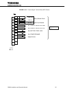
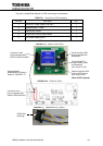
The Power Supply PCB (PSAU-60, designated as PS1) and the Cable1 (designated as
3BBA0083P001) are equipped with G9000 UPS units.
The Cable2 (D-sub 9pin) and the Cable3 (12V power cable) are included in the RemotEyeII
package.
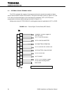
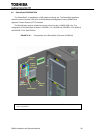
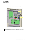
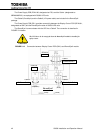
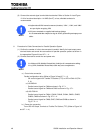
The Power Supply PCB (PS1) provides connectivity between the Display Control PCB (DPAU-81,
designated as SW1) and the RemotEyeII module in G9000 UPS units.
The RemotEye II communicates with the UPS via a Cable2. The connection is described in
FIGURE 2.14 below.
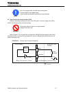
The UPS has to be de-energized when the RemotEyeII module is installed for
safety reason.
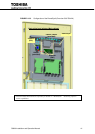
FIGURE 2.14 Connection between Display Control PCB (SW1) and RemotEyeII module
CAUTION
PS1
PSAU-60
RemotEyeII
SW1
DPAU-81
3BBA0083P001
Cable1
D-sub 9-pin Cable
Cable2
12V Power Cable
Cable3
(male)
(RJ45)
(RJ45)
(RJ45)
(receptacle)