


14 G9000 Installation and Operation Manual
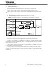
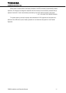
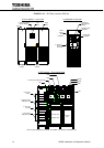
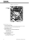
FIGURE 1.4.4 UPS Parts Location (500kVA)
a) UPS cabinet – Front View
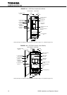
b) Backside of Left Door
Landing
Cabinet
Main
Cabinet
Door
1. LCD Touch Panel
Monitor Display
Left
Door
Right
Door
6. External
Communication
Connector
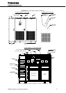
1. LCD Touch
Panel Monitor
Display
4. Main PCB
UPGR-M
2. Display PCB
DPAU-81
Power
Supply
PCB
PSAU-60
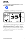
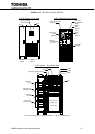
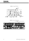
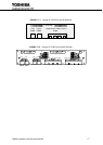
c) UPS cabinet – Front Inside View
9. AC Input
A, B, C
9. Bypass Input
A40, B40, C40
9. DC Input
BP, BN
9. AC Output
A50, B50, C50
52C
CPMS
CPMC
EMB
CB3
52S
3. External I/F PCB (IOAU-09)
CB1
AC Capacitors
Inverter
Unit
Converter Unit
Chopper Unit
AC Capacitors
* Item 10 (Grounding bar) is not shown in FIGURE 1.4.4. (Refer to FIGURE 3.2.3).