


36 G9000 Installation and Operation Manual
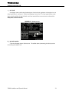
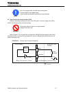
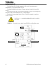
A) Output Contacts (for external alarm annunciation)
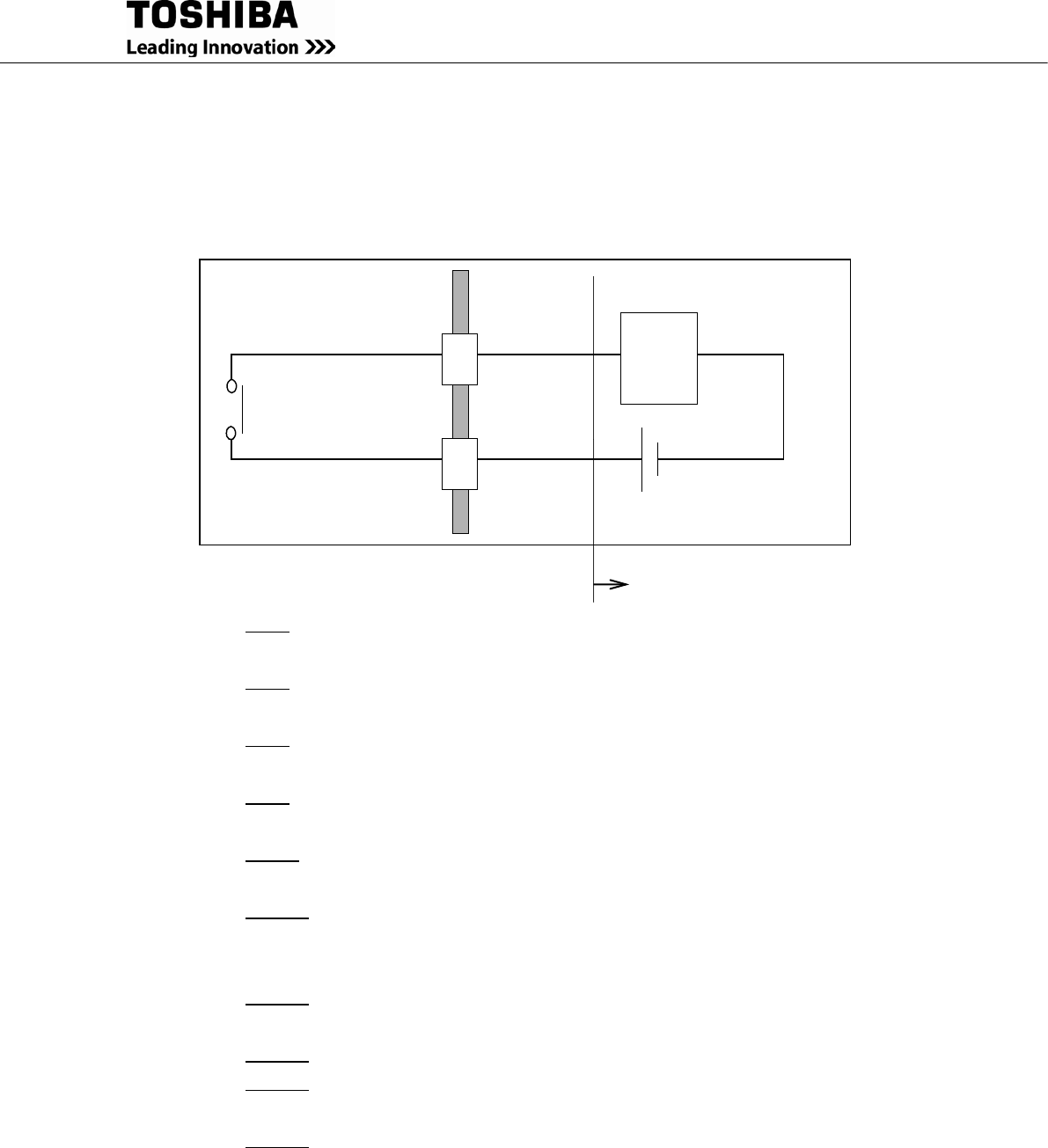
Output contacts consist of form “A”(NO) dry type contacts. Rated capacity of all output contacts is NEC
Class2 (30Vdc/1Adc). All dry contacts should be operated at their rated values or lower. Figure 2.11
illustrates a typical installation. The external relay can also be a lamp, LED, computer, etc.
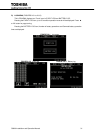
FIGURE 2.11 Control Wiring for External Contacts
Terminal
UPS Cabinet
External to UPS
Cabinet
Relay
Coil
NEC Class 2
Power Source
Relay
Contact
Terminal
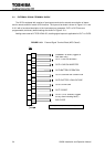
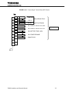
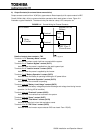
Details of output alarm contacts : TN2
Terminals 1 to 2 "Summary Alarm" contact
Activated only when a major fault has occurred with the system.
Terminals 3 to 4 "Load on Bypass" contact (OUT1)
Activated when the power is supplied from the static bypass input.
Terminals 5 to 6 "Load on Inverter" contact (OUT2)
Activated when the power is supplied by the inverter.
Terminals 7 to 8 "Battery Operation" contact (OUT3)
Activated when the battery is operating following an AC power failure.
Terminals 9 to 10 "Converter Operation" contact (OUT4)
Activated when the converter is operating.
Terminals 11 to 12 "Battery Low Voltage" contact (OUT5)
Activated when the battery voltage drops below discharge end voltage level during inverter
operation (i.e. During AC fail condition).
Terminals 13 to 14 "Overload" contact (OUT6)
Activated when an overload has occurred to the system.
Terminals 15 to 16 "Spare" contact (OUT7)
Terminals 17 to 18 "Total Alarm" contact (OUT8)
Activated by major fault, minor fault and alarm events.
Terminals 19 to 20 "52C Close" contact (OUT9)
Activated when the inverter output contactor 52C has closed. Form “B”(NC).
User supplied