


34 G9000 Installation and Operation Manual
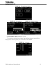
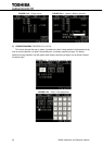
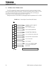
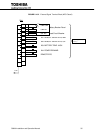
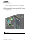
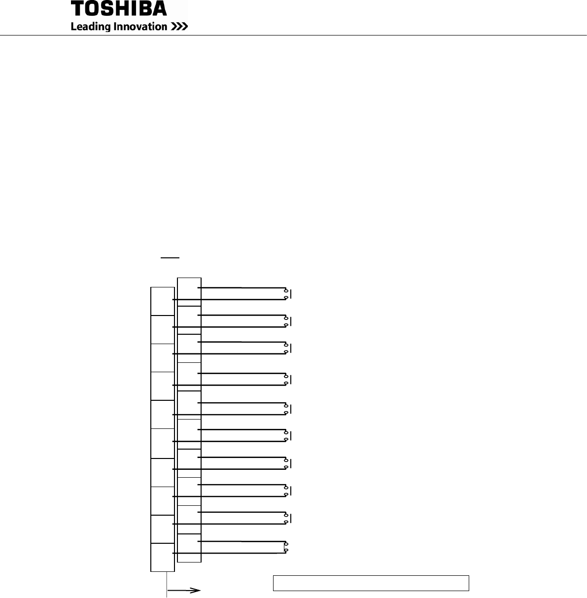
2.4 EXTERNAL SIGNAL TERMINAL BLOCK
The UPS is equipped with a series of input/output terminals for external annunciation of alarms
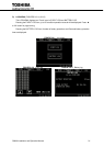
and for remote access of certain UPS functions. The layout of terminals is shown in Figure 2.10.1 and
2.10.2 with a functional description of the input/output port presented. OUT1 to OUT8 are user
programmable, but factory default settings are shown in Figure 2.10.1.
Adding same external I/F PCB “IOAU-09”, doubling signal outputs is applicable for OUT1 to OUT8.
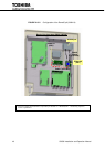
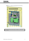
FIGURE 2.10.1 External Signal Terminal Block (NEC Class2)
TN2
SUMMARY ALARM (Triggers on
fault alarm only)
OUT2: LOAD ON INVERTER
OUT3:BATTERY OPERATION
OUT4: CONVERTER OPERATION
OUT5: BATTERY LOW VOLTAGE
OUT6: OVERLOAD
OUT1: LOAD ON BYPASS
UPS
1
3
5
7
9
19
17
15
13
11
2
4
6
8
10
20
18
16
14
12
OUT7: SPARE
OUT8: TOTAL ALARM (Triggers
on any alarm including faults.)
52C CLOSE
*1
*1 Relay contactor (52C close): Normally Closed