


G9000 Installation and Operation Manual 87
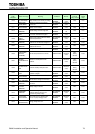
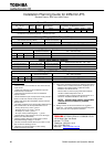
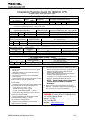
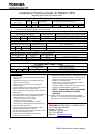
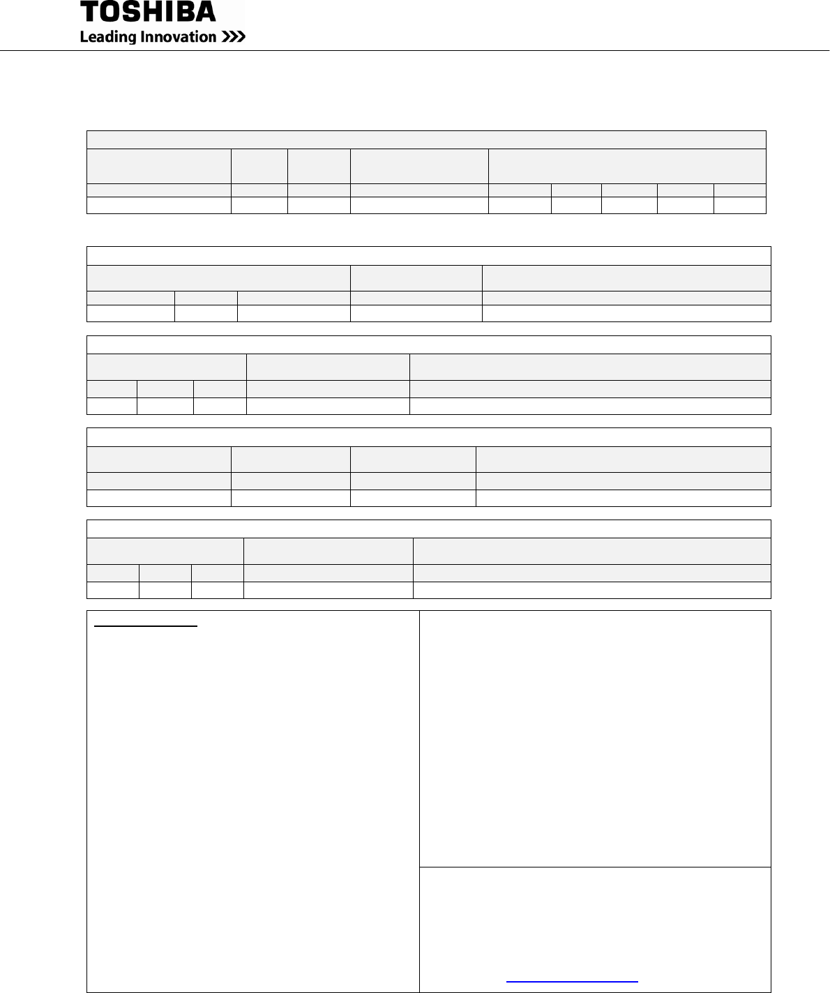
Installation Planning Guide for 160kVA UPS
Standard System: 480V Input, 480V Output
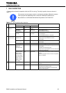
General Mechanical Information
Dimensions
(W x D x H)
Weight
Floor
Loading
Approximate Full-Load
Heat Rejection
Mechanical Clearance (Inches)from UPS
for Ventilation and Maintenance Access
Inches
Lbs.
Lbs./ft.
2
Btu/Hr
Top
Front
Bottom
Sides**
Back
35.4” x 32.8” x 80.6”*
1160
144
17,821
20”
40”
0”
0”
0”
* Height includes removable fan housing – Frame height is 78.7”.
** 0” clearance for peripheral equipment, 1” clearance for walls.
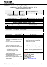
Primary AC Input (480V 3-Phase / 3-Wire)
Maximum Input Power Demand
Normal Mode (Recharge Mode)
Suggested External
Overcurrent Protection
External Feeder Wire Size: Min. – Max. Per Phase
kVA
PF
Amps
Amps
AWG or kcmil at 75º C Temp. Rating
151 (160)
>0.99
181 (192)
250 AT
250 kcmil – 300 kcmil
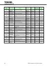
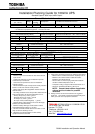
Alternate (Bypass) AC Input (480V 3-Phase / 3-Wire)
Maximum Input Power
Demand
Suggested External
Overcurrent Protection
External Feeder Wire Size:
Min. – Max. Per Phase
kVA PF Amps Amps AWG or kcmil at 75º C Temp. Rating
160
0.9
192
250 AT
250 kcmil – 300 kcmil
Battery Input (480VDC Nominal)
Battery Capacity Required
for Full Load Output
Maximum Discharge
at Full Load Output
Suggested External
Overcurrent Protection
External Feeder Wire Size: Min. – Max.
kWB Amps DC Amps AWG or kcmil at 75º C Temp. Rating
149 @ 0.9 PF
372
400 AT
500 kcmil
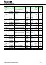
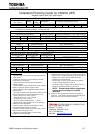
AC Output (480V 3-Phase / 3-Wire)
Rated Output Power
Suggested External
Overcurrent Protection
External Feeder Wire Size:
Min. – Max. Per Phase //
kVA PF Amps Amps AWG or kcmil at 75º C Temp. Rating
160
0.9
192
250 AT
250 kcmil – 300 kcmil
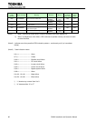
Important Notes:
1. Maximum input current is limited to 106% of the full-load
input current.
2. Output load conductors are to be installed in separate
conduit from input conductors.
3. Control wires and power wires are to be installed in
separate conduits.
4. Recommended AC input and output overcurrent protection
based on continuous full load current per NEC.
5. Wiring shall comply with all applicable national and local
electrical codes.
6. Grounding conductors to be sized per NEC Article 250-
122.
Neutral conductors to be sized per NEC Article 310.15.
- Primary AC Input: 3φ, 3-wire + ground.
- Alternate AC Input: 3φ, 3-wire + ground.
- AC Output: 3φ, 3-wire + ground.
- DC Input: 2-wire (Positive/Negative) + ground.
7. Nominal battery voltage based on the use of VRLA type
batteries (2.0 volts/cell nominal).
8. Maximum battery discharge current based on lowest
permissible discharge voltage of 1.67 VPC.
9. DC wires should be sized to allow not more than a 2-volt
drop at maximum discharge current.
10. Weights do not include batteries or other auxiliary
equipment external to the UPS.
11. Cable sizing calculations based on the following assumptions:
- Minimum size is smallest size based on ampacity at 30 °C.
- Maximum size cable is based on cable bend radius
limitations at the UPS terminals.
- Not more than 3 current-carrying conductors installed in
conduit in ambient temperature of 30 °C.
- Temperature rating of copper conductors/terminals: 75 °C.
- Reference: 2005 NEC Handbook, Table 310.16.
NOTE: Consult latest edition of applicable
national and local codes for possible
variations.
12. Ratings of wires and overcurrent devices are suggested
minimums. Consult with a registered Professional Engineer
within your local area for proper size selections.
TOSHIBA INTERNATIONAL CORPORATION
13131 West Little York Road
Houston, TX 77041
Telephone: (800) 231-1412
Fax: (713) 896-5212
Web Site: www.toshiba.com/ind