


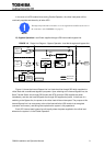
G9000 Installation and Operation Manual 13
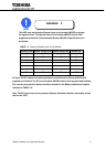
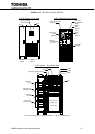
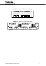
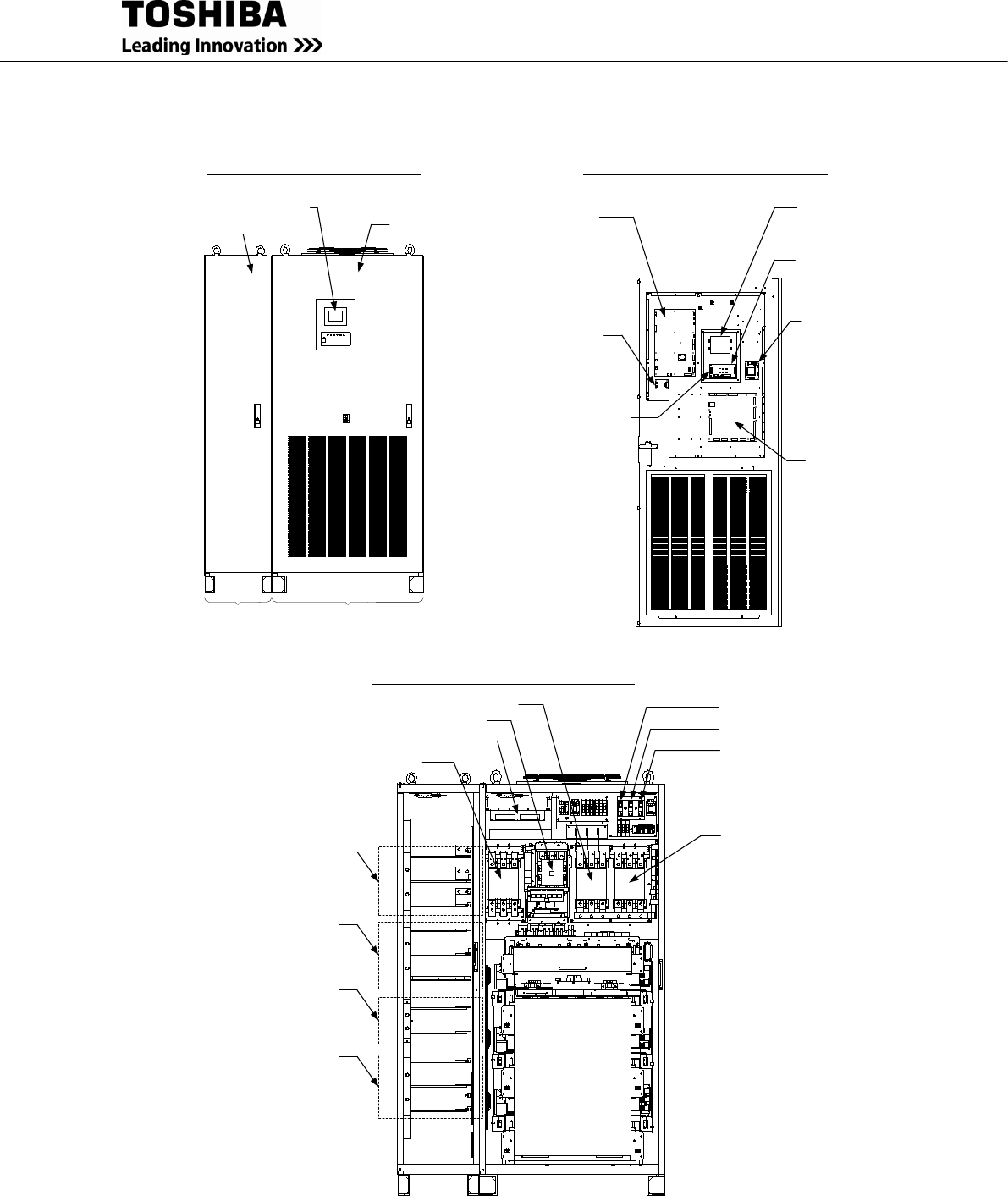
FIGURE 1.4.3 UPS Parts Location (300kVA)
a) UPS cabinet – Front View
b) Door Backside (Main Cabinet)
Landing
Cabinet
Main
Cabinet
1. LCD Touch Panel
Monitor Display
Door
Door
4. Main PCB
UPGR-M
6. External
Communication
Connector
2. Display
PCB
DPAU-81
1. LCD Touch
Panel Monitor
Display
5. Power Supply PCB
PSAU-73
Ground Fault
Sensor
FDAU-04
Power
Supply
PCB
PSAU-60
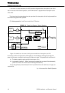
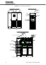
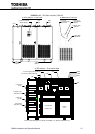
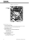
c) UPS cabinet – Front Inside View
9
. AC Input
A, B, C
9. Bypass Input
A40, B40, C40
9. DC Input
BP, BN
9. AC Output
A50, B50, C50
52C
CPMS
CB3
52S
CB1
CPMC
3. External I/F PCB (IOAU-09)
EMB
Converter Unit
Chopper Unit
Inverter Unit
AC Capacitors
* Item 10 (Grounding bar) is not shown in FIGURE 1.4.3. (Refer to FIGURE 3.2.2).