9
8. Install the Profibus network cable through the access holes at the bottom of the
inverter and route the cable in order to make connections to the interface board
connector (CN1). Take care to not route the cable near any sharp edges or in
positions where it may be pinched.
9. Connect the Profibus cable to the interface board connector (CN1). If a ground
cable is going to be used, attach the ground cable to the plated hole near CN1 on
the lower-right portion of the Profibus board (refer to section 3).
CAUTION! Extremely high voltages exist in the area near the Profibus
interface board and connector. Ensure that no stray wires come into contact with
any internal inverter components. Also ensure that the communications cable is
not routed in such a manner that it may come into contact with high-voltage
inverter components, or inverter components that may heat up during operation
and damage the cable insulation.
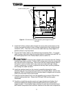
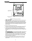
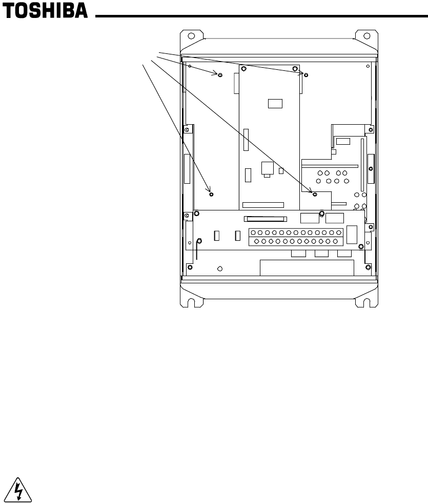
10. Install the interface board into the inverter by carefully aligning the 4 nylon
standoffs with the 4 mounting holes provided in the interface board. Ensure that
connector CN5A on the back side of the interface board is aligned with connector
CN5 on the front side of the control board.
11. Press the interface board firmly onto the standoffs and connector CN5 until the
standoff retaining tabs lock. Ensure that CN5 and CN5A are thoroughly
interlocked.
12. Carefully re-install the operation panel and support bracket and tighten the 4
screws that attach the operation panel support bracket to the control board
support bracket. Once installed, take a moment to verify that all interface board
and network components have sufficient clearance from other drive components.
standoff mounting holes
Figure 2: G3 with front cover and operation panel support bracket
removed


