


22
9.2
9.29.2
9.2
Input (Status) Data Format
Input (Status) Data FormatInput (Status) Data Format
Input (Status) Data Format
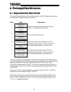
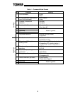
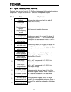
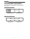
The input data structure from the G3 Profibus interface card to the network master is
comprised of 16 bytes structured as 7 words and 2 independent bytes:
Offset Data Explanation
0
Status word
high byte
1
Status word
low byte
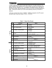
Bit-level drive status word (refer to Table 2 :
Status Word Format)
2
Output frequency
high byte
3
Output frequency
low byte
Drive’s current operating frequency
4
IV input terminal
value high byte
5
IV input terminal
value low byte
Continuously reports the value of the drive’s IV
analog input terminal. 0 ∼ 100% terminal input
corresponds to data values of 0x0000 ∼ 0xFFFF
6
RR input terminal
value high byte
7
RR input terminal
value low byte
Continuously reports the value of the drive’s RR
analog input terminal. 0 ∼ 100% terminal input
corresponds to data values of 0x0000 ∼ 0xFFFF
8
Input terminal
monitor high byte
9
Input terminal
monitor low byte
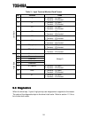
Bit-level status word of drive’s digital input
terminals (refer to Table 3 : Input Terminal
Monitor Word Format)
10
Drive output
current monitor
0x00 ∼ 0xFF corresponds to 0 ∼ 255% drive
rated load current
11
Drive output
voltage monitor
0x00 ∼ 0xFF corresponds to 0 ∼ 255% drive
rated output voltage
12
Parameter number
/ action high byte
13
Parameter number
low byte
Parameter action bits and upper 4 bits of the
parameter register number. Refer to section 10
for a detailed explanation of this data word
14
Parameter data
response high byte
15
Parameter data
response low byte
During parameter register reads, this word
contains the requested data response. Refer to
section 10 for a detailed explanation of this data
word