


2
Usage Precautions
•= Please use the interface only when the ambient temperature of the inverter unit into
which the interface is installed is within the following specified temperature limits:
Operation
: -10 ∼ +40°C (+14 ∼ +104°F)
Storage
: -25 ∼ +65°C (-13 ∼ +149°F)
•= Avoid installation locations that may be subjected to large shocks or vibrations.
•= Avoid installation locations that may be subjected to rapid changes in temperature or
humidity.
Operating Environment
Operating EnvironmentOperating Environment
Operating Environment
•= Do not touch charged parts such as the terminal block while the inverter’s CHARGE
lamp is lit. A charge will still be present in the inverter unit’s internal electrolytic
capacitors, and therefore touching these areas may result in an electrical shock.
Always turn all inverter input power supplies OFF, and wait at least 5 minutes after the
CHARGE lamp has gone out before connecting communication cables or motor wiring.
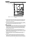
•= When installing the interface board into the inverter and making wiring connections,
make certain that no clippings or wiring leads that could cause device failure fall into
the inverter or onto electronic components.
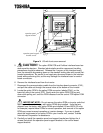
•= Proper ground connections are vital for both safety and signal reliability reasons. For
proper grounding procedures, please refer to the section in this manual pertaining to
grounding (section 3).
•= Route the communication cables separate from the inverter input/output power wiring.
•= To avoid the possibility of electric shock due to leakage currents, always ground the
inverter unit’s E/GND terminal and the motor. To avoid misoperation, do not connect
the Profibus interface board's shield terminal to either of the above-mentioned grounds
or any other power ground.
Installation
Installation Installation
Installation •
••
• Wiring
Wiring Wiring
Wiring
•= The inverter’s EEPROM has a life span of 10,000 write cycles. Do not write to the
same parameter register more than 10,000 times.
•= Do not touch or insert a rod or any other item into the inverter while power is applied,
as this may lead to electrical shock or inverter damage.
•= Commission the disposal of the interface board to a specialist.
•= Do not assign the same address to more than one inverter in the same network.
•= Individual slave addresses can be set from 0 ∼ 125. Addresses 126 and above are
invalid, and will cause the inverter to trip "OPTION PCB ERROR".
•= When the inverter’s control power supply is turned on, the inverter performs
initialization functions for approximately 2 seconds, during which communications
capabilities are disabled. Communications capabilities will also be disabled for
approximately 2 seconds after momentary control power supply outages or inverter
resets.
Other Precautions
Other PrecautionsOther Precautions
Other Precautions