


8
6.
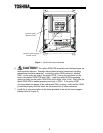
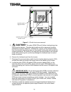
CAUTION! The option ROM PCB assembly and interface board are
static-sensitive devices. Standard electrostatic-sensitive component handling
precautions should be observed. Locate the option ROM connector, labeled
CN41, on the lower-left side of the control PCB. Line up the connector on the
back of the option ROM PCB with CN41. Install the option ROM by pressing
gently but firmly on the option ROM PCB until a slight “click” is felt. Verify that the
option ROM PCB is seated properly and firmly in CN41. If the option ROM
connector does not appear to be mating with CN41 properly, verify that the ROM
is oriented properly and that there are no obstructions in either connector.
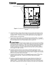
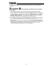
7. Install the 4 nylon standoffs into the holes provided in the control board support
bracket (refer to Figure 2).
operation panel support
bracket screws
operation panel
support bracket
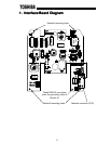
Figure 1: G3 with front cover removed