


11
2.3
2.32.3
2.3
Removal
RemovalRemoval
Removal
Removal of the Profibus interface board from a TOSVERT-130 G3 inverter should
only be performed by a qualified technician familiar with the maintenance and
operation of the G3. In order to protect the interface board connector’s reliability, do
not repeatedly connect and disconnect the interface. Use the following procedure if it
becomes necessary to remove the Profibus interface board from the inverter.
CAUTION! Do not remove the interface board while power is applied to
the inverter. Removing the interface board with power applied may damage the
inverter.
2.3.1
2.3.12.3.1
2.3.1
Before Removal
Before RemovalBefore Removal
Before Removal
The inverter will display an error message if the option ROM becomes dislodged or is
removed from its socket. The inverter must be reset to clear this error. Therefore, all
parameters will be automatically reset to the factory default values after an option
ROM has been removed from the inverter. If it is desired to retain the current
parameter settings, the user should access the user-changed parameter group to
display and record all the parameters and setting values that have been changed
from factory defaults. Even if the current settings are saved using the TYPE 5
RESET function, they will be erased from memory during the re-initialization of the
inverter after the option ROM has been removed.
2.3.2
2.3.22.3.2
2.3.2
Removal Procedure
Removal ProcedureRemoval Procedure
Removal Procedure
1. CAUTION! Verify that all input power sources to the inverter have
been turned OFF and are locked and tagged out.
2.
DANGER! Wait at least 5 minutes for the inverter’s electrolytic
capacitors to discharge before proceeding to step 3. Do not touch any internal
parts with power applied to the inverter, or for at least 5 minutes after
power to the inverter has been removed. A hazard exists temporarily for
electrical shock even if the source power has been removed.
3.
Remove the inverter’s cover (open the door on units with hinged doors).
Verify that the CHARGE LED has gone out before continuing the removal
process.
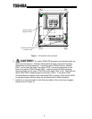
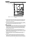
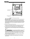
4. Loosen the 4 screws attaching the operation panel support bracket to the control
board support bracket and remove the operation panel and support bracket as a
unit (refer to Figure 3).