


20
9.
9.9.
9.
Exchanged Data Structures
Exchanged Data StructuresExchanged Data Structures
Exchanged Data Structures
9.1
9.19.1
9.1
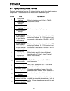
Output (Control) Data Format
Output (Control) Data FormatOutput (Control) Data Format
Output (Control) Data Format
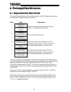
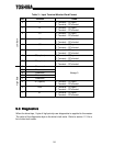
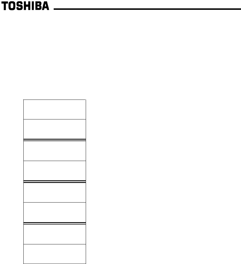
The output data structure from the network master to the G3 Profibus interface card
is comprised of 8 bytes structured as 4 words:
Offset Data Explanation
0
Command word
high byte
1
Command word
low byte
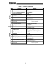
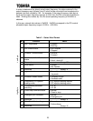
Bit-level drive control command word (refer to
Table 1 : Command Word Format)
2
Frequency
command high byte
3
Frequency
command low byte
Drive’s frequency command
4
Parameter number
/ action high byte
5
Parameter number
low byte
Parameter action bits and upper 4 bits of the
parameter register number. Refer to section 10
for a detailed explanation of this data word
6
Parameter data to
write high byte
7
Parameter data to
write low byte
During parameter register writes, this word
contains the data to write. Refer to section 10
for a detailed explanation of this data word
The data contained in the frequency command word must be the desired frequency
command multiplied by 100, and then converted to hexadecimal. In other words, if a
frequency command of 55.34Hz is desired, then 55.34 x 100 = 5534, which
converted to hexadecimal is 0x159E. The frequency command high byte (offset 2)
must therefore contain 0x15, and the frequency command low byte (offset 3) must
contain 0x9E.
In this way, the G3’s allowable frequency command range of 0.00Hz ∼ 400.00Hz
equates to network values of 0x0000 ∼ 0x9C40.
Regardless of the frequency command value sent via the Profibus network to the
drive, the actual operating frequency of the drive will still be limited locally by the
LOWER LIMIT FREQUENCY, UPPER LIMIT FREQUENCY, and MAXIMUM OUTPUT
FREQUENCY parameter settings.