


12
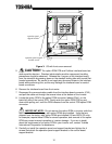
5. CAUTION! The option ROM PCB and Profibus interface board are
static-sensitive devices. Standard electrostatic-sensitive component handling
precautions should be observed. Release the 4 corners of the interface board
from the standoffs by pressing down on the standoff locking tabs with a small flat-
headed screwdriver. Be careful to not apply any abnormal stress to the interface
board while performing this, as this may damage the interface board or control
board connectors.
6. Remove the interface board from the inverter.
7. Disconnect the communications cable from the interface board connector (CN1),
and pull the cable out through the access holes at the bottom of the inverter.
8. Locate the option ROM in the option ROM connector, labeled CN41, on the
lower-left side of the control PCB. Gently work the option ROM PCB up and
down while pulling on it until the ROM releases from the control PCB option ROM
connector.
IMPORTANT NOTE: Do not remove the option ROM on inverter units that
were received from the factory with option ROMs pre-installed. Units that are
shipped from the factory with option ROMs pre-installed (H3 and 600V G3 units,
for example) require these ROMs for correct operation, and removal of the option
ROM may cause incorrect operation or inverter damage. If you are in doubt
about the requirement of an option ROM in your inverter unit, contact Toshiba
International Corporation for assistance.
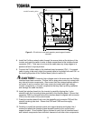
9. Carefully re-install the operation panel and support bracket and tighten the 4
screws that attach the operation panel support bracket to the control board
support bracket.
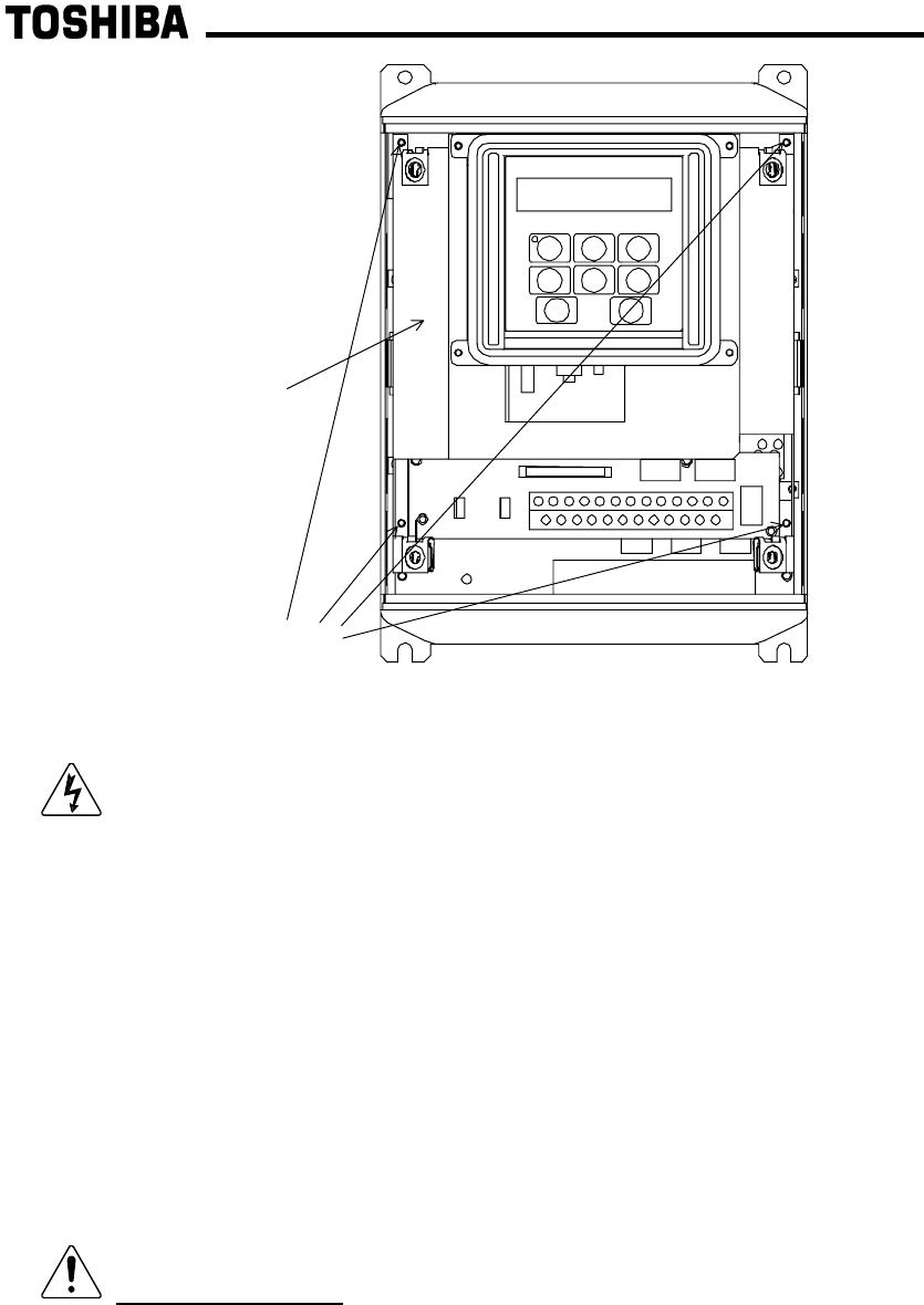
operation panel support
bracket screws
operation panel
support bracket
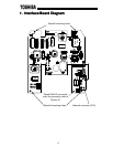
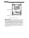
Figure 3: G3 with front cover removed