


19
Indicators
1 green LED is provided to indicate when the interface has achieved the
DATA_EXCHANGE state with the network master. This serves as a convenient
indicator that the master and drive are configured properly and are exchanging data.
Isolation
The network interface portion of the Profibus-DP board is fully optically-isolated for
optimal noise-immunity characteristics.
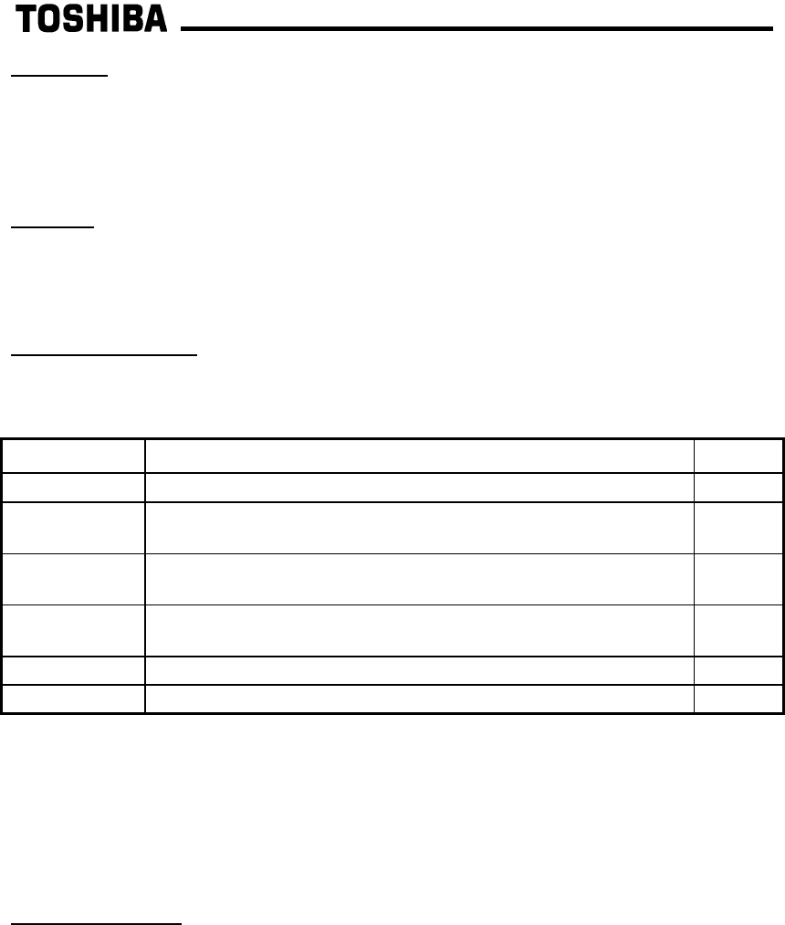
Network Connector
The network interface is a standard DB9 connector with the following signals
provided:
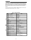
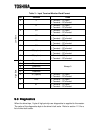
Pin Number Function In/Out
3 Profibus network “B” (positive) data line In/out
4 RTS signal – direction control for fiber optic network
interface
Out
5 DGND – power supply ground internally connected to the
interface board’s isolated ground
-
6 VP – power supply +5v internally connected to the
interface board’s isolated P5.
-
8 Profibus network “A” (negative) data line In/out
1, 2, 7, 9 No connection -
In addition to the above signals, the metallic housing of the DB9 connector is
connected to the shield section of the interface board. The shield section contains a
plated connection point where a ground wire can be attached to connect the network
cable shield to ground. Refer to section 3 of this document for more information
related to grounding.
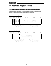
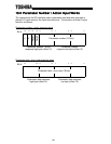
Input/Output Data
The interface’s cyclic data sizes are fixed at 8 bytes of output (control) data
configured as 4 words, and 16 bytes of input (status) data configured as 7 words and
2 bytes. For detailed explanations of the format and usage of this data, refer to
sections 9 and 10 of this document.