95
8300 Using ViewRTU
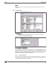
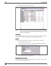
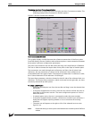
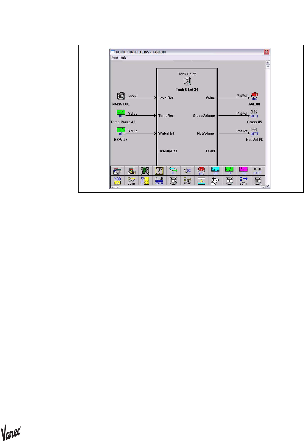
Displaying the Point Connections window.
• Double-click on one of the icons to display the Point Connections window. The
following example Point Connections window appears.
Figure 6-39:Point Connections Window
Point Connections Window
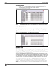
This graphic display visually illustrates the reference connections of the focus point.
From this display, the user is able to select reference points, create connections between
these points, and enter configuration parameters.
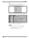
The point icons located in the Icon Bar utilize the drag-and-drop features of Windows.
The user is able to connect the output data of one point to the input of another point.
The connections are made through point references and links. Not all points have
references, but any parameter of a point can be referenced. Some references are
incompatible with some types of data. The program can determine if a reference is valid,
but it cannot determine if the reference is meaningful.
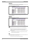
The Input Data parameters, which are located on the left side of the software block, are
references. The Output Data parameters, which are located on the right side, are most
commonly referenced by other points.
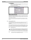
To create a Connection:
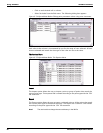
• Select the desired point icon from the Icon Bar and drag it onto the desired data
parameter.
• If the point dropped does not exist, then the user needs to define the point as
described in the previous section. The same configuration process is used to
define the point.
• If multiple points exist, the user is prompted to select the point number.
• If the point dropped already contains a reference to another input reference, a
dialog box will appear inquiring whether or not to overwrite the existing
reference.
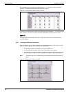
• The point icon will appear to the right or left of the selected arrow as seen
Figure 6-44.
Note! Double-left clicking on a focus point icon allows the user to view the point’s Edit Point
window.


