Hardware TankGate Interface
14 Installation and Operations Manual
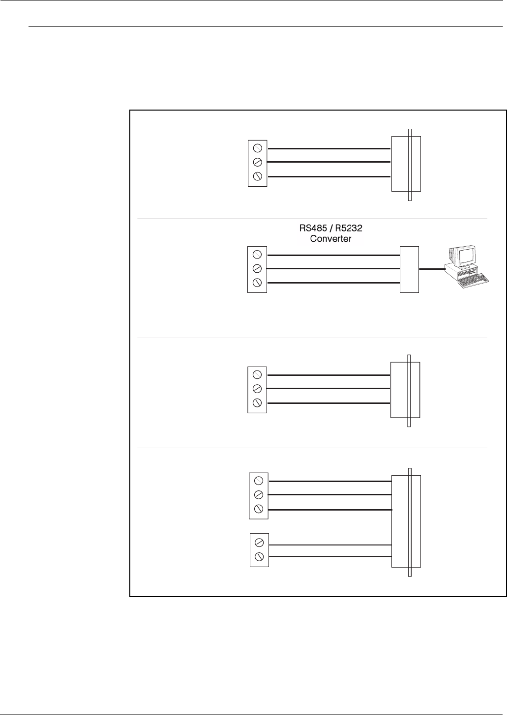
2.3 TankGate Communications Cable
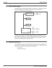
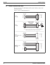
The layout for the RS-232 cable between the PC and the TankGate is shown in the
following illustrations
Figure 2-14:Com 1 Cable without RTS/CTS
TANK GATE
J7
PC
Com 0
(RS-232)
TXD
RXD
GND
2
3
5
DB9 Female
Pin Signal
2
3
5
RXD
TXD
GND
NOTE! Signals on RS485 / RS232 converter may have different designations.
Refer to OFM manual for the converter for more information.
A
B
GND
TANK GATE
R5485 / R5238
Converter
J6
PC
A
B
GND
Com 1
(RS485)
TANK GATE
J6
PC
Com 1
without RTS / CTS
(RS-232)
TXD
RXD
GND
2
3
5
DB9 Female
Pin Signal
2
3
5
RXD
TXD
GND
TANK GATE
J6
DCE
Com 1
with RTS / CTS
(RS-232)
TXD
RXD
GND
3
2
5
DB9 Male
Pin Signal
2
3
5
RXD
TXD
GND
8
7
RTS
CTS
J7
7
8
RTS
CTS


