24 www.xilinx.com ML605 Hardware User Guide
UG534 (v1.2.1) January 21, 2010
Chapter 1: ML605 Evaluation Board
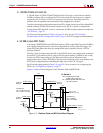
5. System ACE CF and CompactFlash Connector
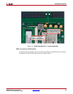
The Xilinx System ACE CompactFlash (CF) configuration controller allows a Type I or
Type II CompactFlash card to program the FPGA through the JTAG port. Both hardware
and software data can be downloaded through the JTAG port. The System ACE CF
controller supports up to eight configuration images on a single CompactFlash card. The
configuration address switches allow the user to choose which of the eight configuration
images to use.
The CompactFlash (CF) card shipped with the board is correctly formatted to enable the
System ACE CF controller to access the data stored in the card. The System ACE CF
controller requires a FAT16 file system, with only one reserved sector permitted, and a
sector-per-cluster size of more than one (UnitSize greater than 512). The FAT16 file system
supports partitions of up to 2 GB. If multiple partitions are used, the System ACE CF
directory structure must reside in the first partition on the CompactFlash, with the
xilinx.sys file located in the root directory. The xilinx.sys file is used by the System
ACE CF controller to define the project directory structure, which consists of one main
folder containing eight sub-folders used to store the eight ACE files containing the
configuration images. Only one ACE file should exist within each sub-folder. All folder
names must be compliant to the DOS 8.3 short file name format. This means that the folder
names can be up to eight characters long, and cannot contain the following reserved
characters: < > " / \ |. This DOS 8.3 file name restriction does not apply to the actual ACE
file names. Other folders and files may also coexist with the System ACE CF project within
the FAT16 partition. However, the root directory must not contain more than a total of 16
folder and/or file entries, including deleted entries. When ejecting or unplugging the
CompactFlash device, it is important to safely stop any read or write access to the
CompactFlash device to avoid data corruption.
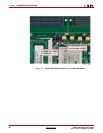
System ACE CF error and status LEDs indicate the operational state of the System ACE CF
controller:
• A blinking red error LED indicates that no CompactFlash card is present.
• A solid red error LED indicates an error condition during configuration.
• A blinking green status LED indicates a configuration operation is ongoing.
• A solid green status LED indicates a successful download.
Note:
Jumper J69 can be removed to disable the Red Error LED circuit. It is recommended that this
jumper is installed during operations utilizing the CompactFlash card.
Every time a CompactFlash card is inserted into the System ACE CF socket, a
configuration operation is initiated. Pressing the System ACE CF reset button re-programs
the FPGA.
Note:
System ACE CF configuration is enabled by way of DIP switch S1. See “18. Switches,”
page 53 for more details.
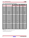
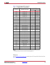
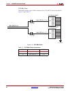
The System ACE CF MPU port is connected to the FPGA. This connection allows the FPGA
to use the System ACE CF controller to reconfigure the system or access the CompactFlash
card as a generic FAT file system.


