


1
Outline
1-3
3. Names of each part on the CC-Link compatible module
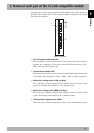
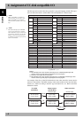
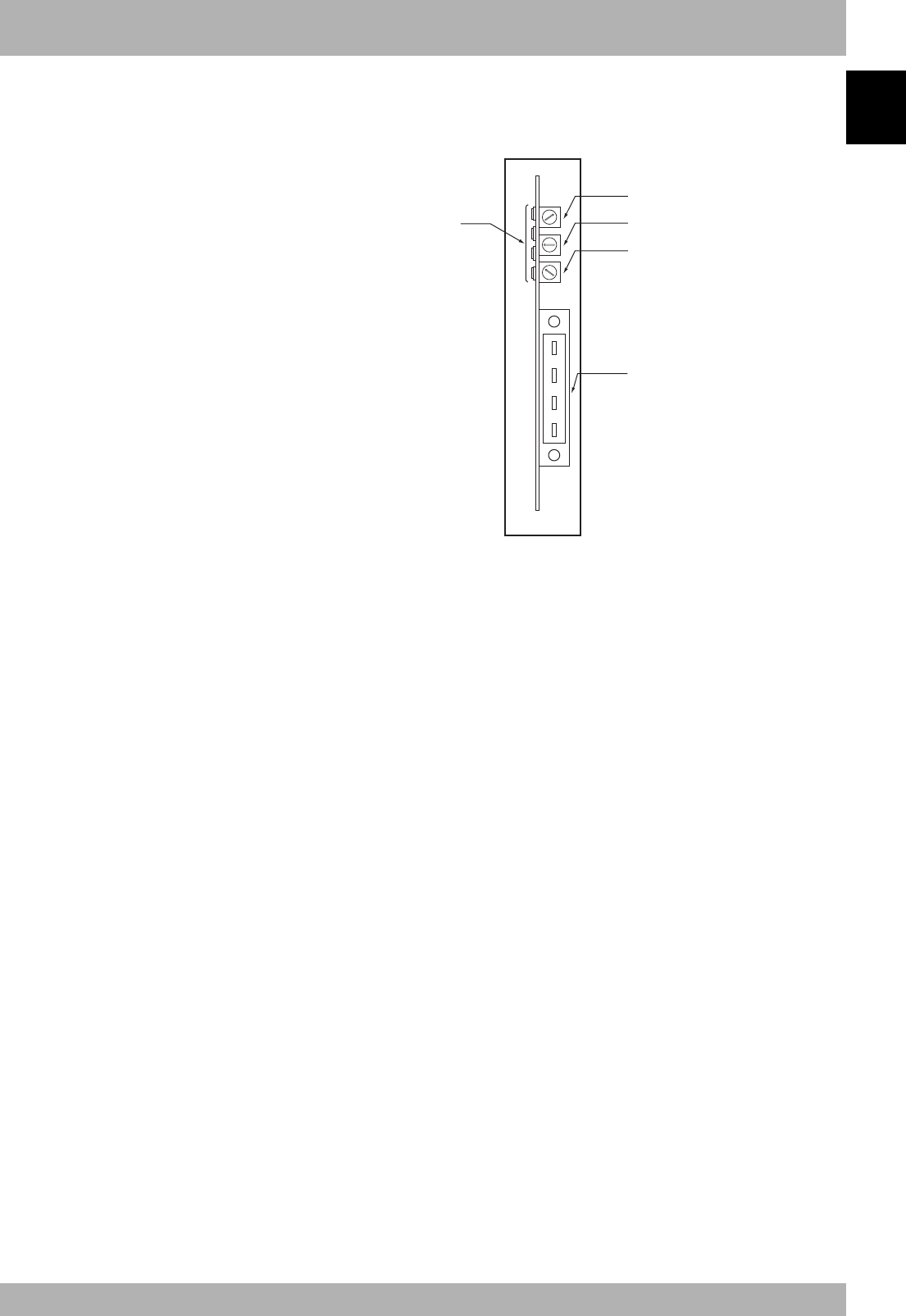
The part names of the CC-Link compatible module installed in the robot controller are
described in this section. The CC-Link compatible module is installed into an optional
slot in the robot controller.
w
t
r
e
q
1
2
3
4
5
6
7
8
9
0
1
2
3
4
5
6
7
8
9
0
1
2
3
4
5
6
7
8
9
0
Front of the unit
q CC-Link system cable terminals
These terminals are used to connect the CC-Link system cable. Each of the four
terminals has a meaning, so do not make miswiring. These terminals are “DA”,
“DB”, “DG” and “SLD” from the top.
w Transmission monitor LED
The status in the CC-Link system is indicated with ON, OFF and flickering status
of four LEDs. These terminals are “RUN”, “ERRL”, “SD” and “RD” from the top.
e Station No. setting switch (LSB: 1st digit)
This is the rotary switch for setting the robot controller station No. in the CC-Link
system. The 1st digit of the station No. is set with this switch.
r Station No. setting switch (MSB: 2nd digit)
This is the rotary switch for setting the robot controller station No. in the CC-Link
system. The 2nd digit of the station No. is set with this switch.
t Communication speed switch (BPS)
This is the rotary switch for setting the CC-Link system’s communication speed.