


Outline
1
1-4
4. Assignment of CC-Link compatible I/O
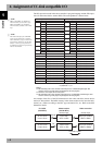
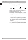
The I/O expressions used in the robot controller’s program language and the I/O expres-
sions for the remote device stations differ. The correspondence is shown below.
n: Address assigned to master module with station No. setting
n= (station No. - 1) ✕ 2
SOW(0)
*3
RWr0 SIW(0)
*3
RWw0
SOW(1)
*3
RWr1 SIW(1)
*3
RWw1
SOD(2) SOW(2) RWr2 SID(2) SIW(2) RWw2
SOW(3) RWr3 SIW(3) RWw3
SOD(4) SOW(4) RWr4 SID(4) SIW(4) RWw4
SOW(5) RWr5 SIW(5) RWw5
SOD(6) SOW(6) RWr6 SID(6) SIW(6) RWw6
SOW(7) RWr7 SIW(7) RWw7
SOD(8) SOW(8) RWr8 SID(8) SIW(8) RWw8
SOW(9) RWr9 SIW(9) RWw9
SOD(10) SOW(10) RWrA SID(10) SIW(10) RWwA
SOW(11) RWrB SIW(11) RWwB
SOD(12) SOW(12) RWrC SID(12) SIW(12) RWwC
SOW(13) RWrD SIW(13) RWwD
SOD(14) SOW(14) RWrE SID(14) SIW(14) RWwE
SOW(15) RWrF SIW(15) RWwF
SO0(7~0)
*1
RXn7~RXn0 SI0(7~0)
*1
RYn7~RYn0
SO1(7~0)
*1
RXnF~RXn8 SI1(7~0)
*1
RYnF~RYn8
SO2(7~0) RX(n+1)7~RX(n+1)0 SI2(7~0) RY(n+1)7~RY(n+1)0
SO3(7~0) RX(n+1)F~RX(n+1)8 SI3(7~0) RY(n+1)F~RY(n+1)8
SO4(7~0) RX(n+2)7~RX(n+2)0 SI4(7~0) RY(n+2)7~RY(n+2)0
SO5(7~0) RX(n+2)F~RX(n+2)8 SI5(7~0) RY(n+2)F~RY(n+2)8
SO6(7~0) RX(n+3)7~RX(n+3)0 SI6(7~0) RY(n+3)7~RY(n+3)0
SO7(7~0) RX(n+3)F~RX(n+3)8 SI7(7~0) RY(n+3)F~RY(n+3)8
SO10(7~0) RX(n+4)7~RX(n+4)0 SI10(7~0) RY(n+4)7~RY(n+4)0
SO11(7~0) RX(n+4)F~RX(n+4)8 SI11(7~0) RY(n+4)F~RY(n+4)8
SO12(7~0) RX(n+5)7~RX(n+5)0 SI12(7~0) RY(n+5)7~RY(n+5)0
SO13(7~0) RX(n+5)F~RX(n+5)8 SI13(7~0) RY(n+5)F~RY(n+5)8
SO14(7~0) RX(n+6)7~RX(n+6)0 SI14(7~0) RY(n+6)7~RY(n+6)0
SO15(7~0) RX(n+6)F~RX(n+6)8 SI15(7~0) RY(n+6)F~RY(n+6)8
------------ RX(n+7)F~RX(n+7)0
*2
------------ RY(n+7)F~RY(n+7)0
*2
Output from robot controller Input to robot controller
Program language
Remote device station
Program language
Remote device station
Caution)
*1: Has a meaning in the robot controller’s internal process as a dedicated input/output. This
cannot be used as a general-purpose input/output in the robot program.
*2: This area is reserved for the CC-Link system.
*3: Has a meaning in the robot controller’s internal process as a dedicated command region. This
cannot be used as a general-purpose input/output in the robot program.
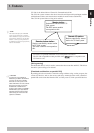
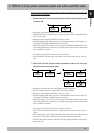
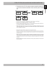
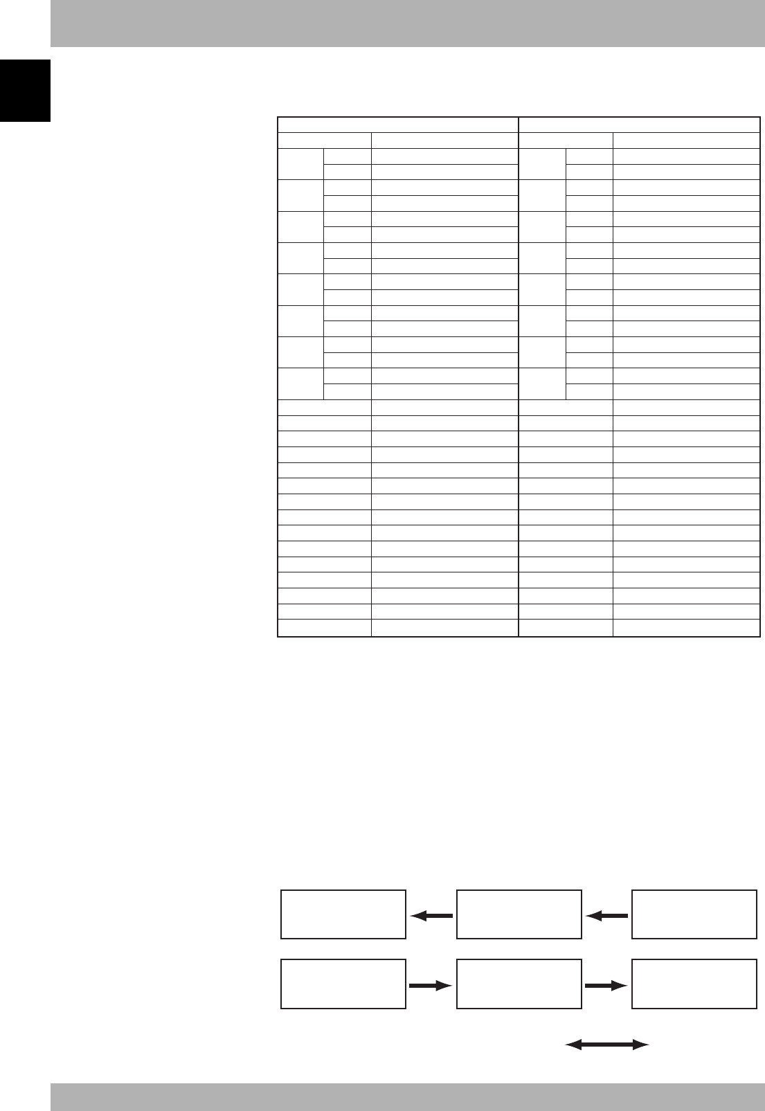
An example of the flow of the I/O information in the robot controller (remote device
station) is shown below. The buffer memory in the master station used to store the infor-
mation, etc., differs according to the PLC type and station No., etc. Refer to the PLC
Manual for details.
X17F to X100
D115 to D100
E7h to E0h
2EFh to 2E0h
FROM
TO
RX(n+7)F to RXn0
RWrF to RWr0
RY(n+7)F to RYn0
RWwF to RWw0
Y17F to Y100
D135 to D120
167h to 160h
1EFh to 1E0h
PLC CPU
(A1SHCPU)
Master station
(A1SJ61BT11)
Robot controller
Automatic update
Remote input Remote input
n
NOTE
SIW(n) and SOW(n) are handled as
numerical data of word with no sign.
SID(n) and SOD(n) are handled as
numerical data of double words with a
sign.
n
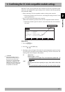
NOTE
The dedicated input of the STD.DIO
connector provided on the controller
will be disabled except for an interlock
signal (DI 11). When the external 24V
monitor control of system parameters
is disabled, the interlock signal (DI 11)
will also be disabled.