


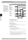


5-12
Specifications
5
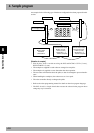
4. Sample program
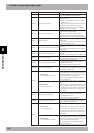
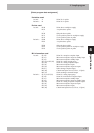
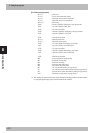
[PLC data assignment]
X0 (*1) : Unit error
X1 (*1) : Local station data link status
X6 (*1) : Data link start normal completion
X7 (*1) : Data link start error completion
X0F (*1) : Unit ready
X100 : 1st unit’s SO(00): Emergency stop input status
X101 : 1st unit’s SO(01): CPU_OK
: :
X17F : 1st unit reservation
X180 : 2nd unit’s SO(00): Emergency stop input status
X181 : 2nd unit’s SO(01): CPU_OK
: :
X1FF : 2nd unit reservation
Y0 (*1) : Refresh instruction
Y6 (*1) : Data link start request
Y100 : 1st unit’s SI(00): Emergency stop input
Y101 : 1st unit’s SI(01): Servo ON input
: :
Y17F : 1st unit reservation
Y180 : 2nd unit’s SI(00): Emergency stop input
Y181 : 2nd unit’s SI(01): Servo ON input
: :
Y1FF : 2nd unit reservation
M0 : Unit preparation complete flag
M1 : Parameter setting flag
M2 : Data link start flag
M4 : 1st station data link status
M8 : 5th station data link status
D0 : No. of connection units storage device
D1 : 1st unit local station information setting storage device
D2 :
2nd unit local station information setting storage device
D10 : Parameter setting status storage device
*1: This number is determined by the master module mounting position and the number
of occupied input/output points mounted before the module.