


5-7
5
Specifications
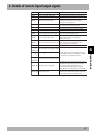
3. Dedicated input/output signal timing chart
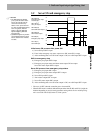
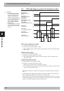
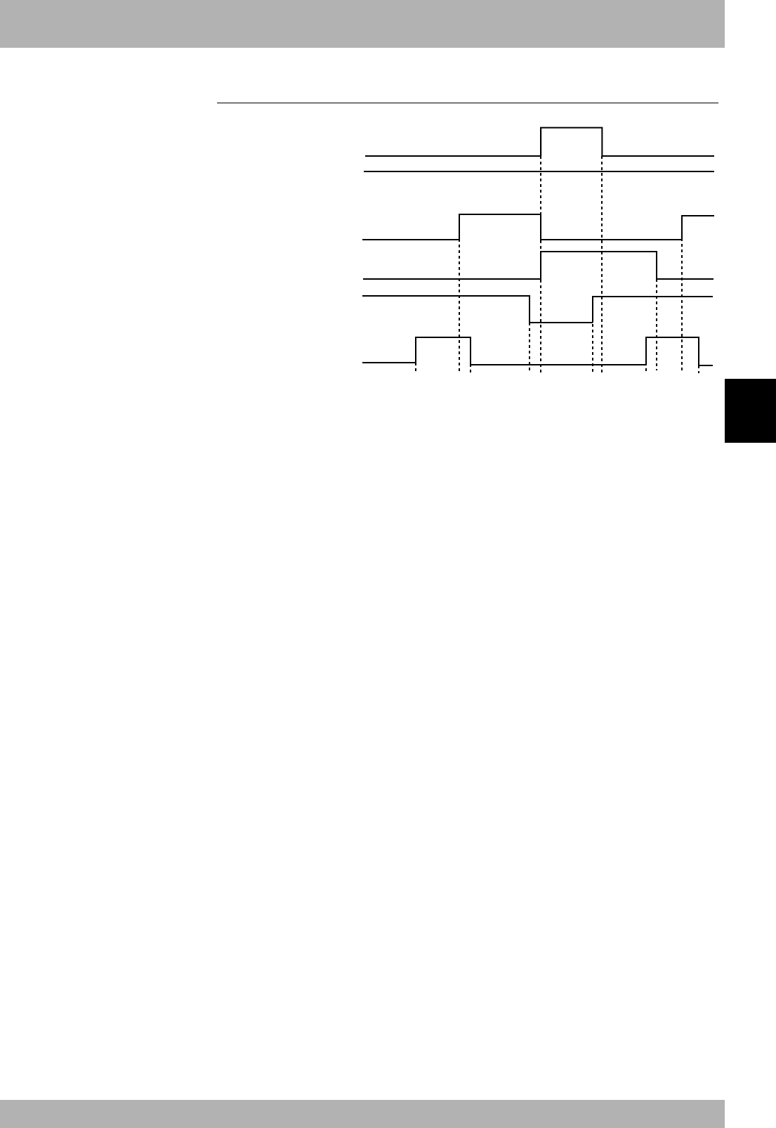
3.2 Servo ON and emergency stop
a) b) c) d) e) f) g) h) i) j) k)
on
on
off
on
off
on
off
on
on
off
off
off
RXn0:SO
(
00
)
Emergency stop input
status output
RXn1:SO
(
01
)
CPU_OK output
RXn2:SO
(
02
)
Servo ON status output
RXn3:SO
(
03
)
Alarm status output
RYn0:SI
(
00
)
Emergency stop input
RYn1:SI
(
01
)
Servo ON input
Initial servo ON process after power ON
a) Servo ON input ON is input
b) If not in the emergency stop state, output servo ON status ON is output
c) After confirming that servo ON status output is ON, servo ON input OFF is input
Shift to emergency stop
d) Emergency stop input OFF is input
e) Emergency stop input status and alarm status output ON are output
Servo ON status output OFF is output
Servo ON process from emergency stop status
f) Emergency stop input ON is input
g) Emergency stop input status output OFF is output
h) Servo ON input ON is input
i) Alarm status output OFF is output
j) Servo ON status output ON is output
k) After confirming that servo ON status output is ON, servo ON input OFF is input
* The servo is OFF when the controller power is turned ON.
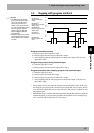
* When SAFE mode is enabled, dedicated inputs other than SI (00) and SI (11) might be
disabled depending on service mode parameter setting unless service mode input sig-
nal is set to ON with SI (02) in the CC-Link system.
c
CAUTION
• The dedicated input ON/OFF
process from the master station
PLC to the controller must be
carried out at an interval of
100ms or more. If the interval is
too short, the dedicated input may
not be recognized. (This also
applies to the same dedicated
input and differing dedicated
input intervals.)
• If dedicated outputs are provided
for the dedicated inputs from the
master station PLC to controller,
use them.