


4-1
4
Troubleshooting
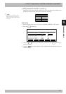
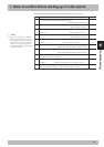
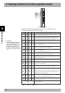
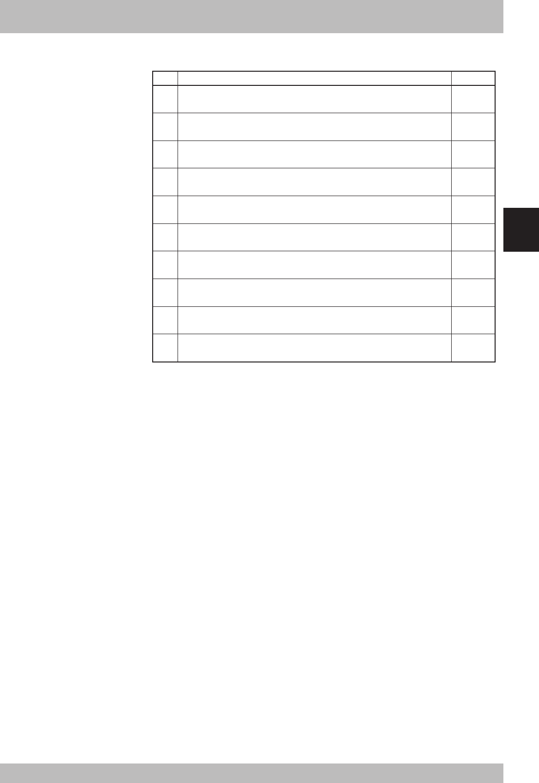
1. Items to confirm before starting up CC-Link system
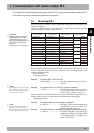
Confirm the following items before starting up the CC-Link system.
1
2
3
4
5
6
7
8
9
10
Confirmation details Check
Is the CC-Link compatible module accurately connected?
(Refer to Chapter 2 section 2 or 3.)
Is the robot controller set to the CC-Link system specifications?
(Refer to Chapter 2 section 1.)
Are the CC-Link compatible module station No. and communication speed
correctly set? (Refer to Chapter 2 section 1.)
Is the ferrite core connected to the power input cable to the robot controller?
(Refer to Chapter 2 section 4.)
Is the CC-Link system cable accurately connected to the CC-Link compatible
module? (Refer to Chapter 2 section 5.)
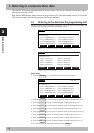
Was the line test from the master station PLC correct?
(Refer to the master station PLC instruction manual.)
Is the master station PLC set for the 4-station occupying remote device?
(Refer to the master station PLC instruction manual.)
Is the master station PLC exchanging the data for four stations? (The data for four
stations must always be exchanged.)
Has the initial data process been carried out between the master station and robot
controller? (Refer the initialization process in Chapter 3 section 2.)
Is the master station PLC judging that the robot controller is correctly functioning using
RX(n+7)8 (remote station Ready)? (Refer the samples in Chapter 5 section 4.)
n
NOTE
The dedicated input of the STD.DIO
connector provided on the controller
will be disabled except for an interlock
signal (DI 11). When the external 24V
monitor control of system parameters
is disabled, the interlock signal (DI 11)
will also be disabled.