


106 CHAPTER 3: MULTIFUNCTIONAL INTERFACE MODULES
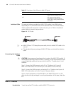
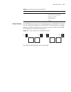
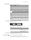
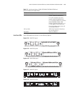
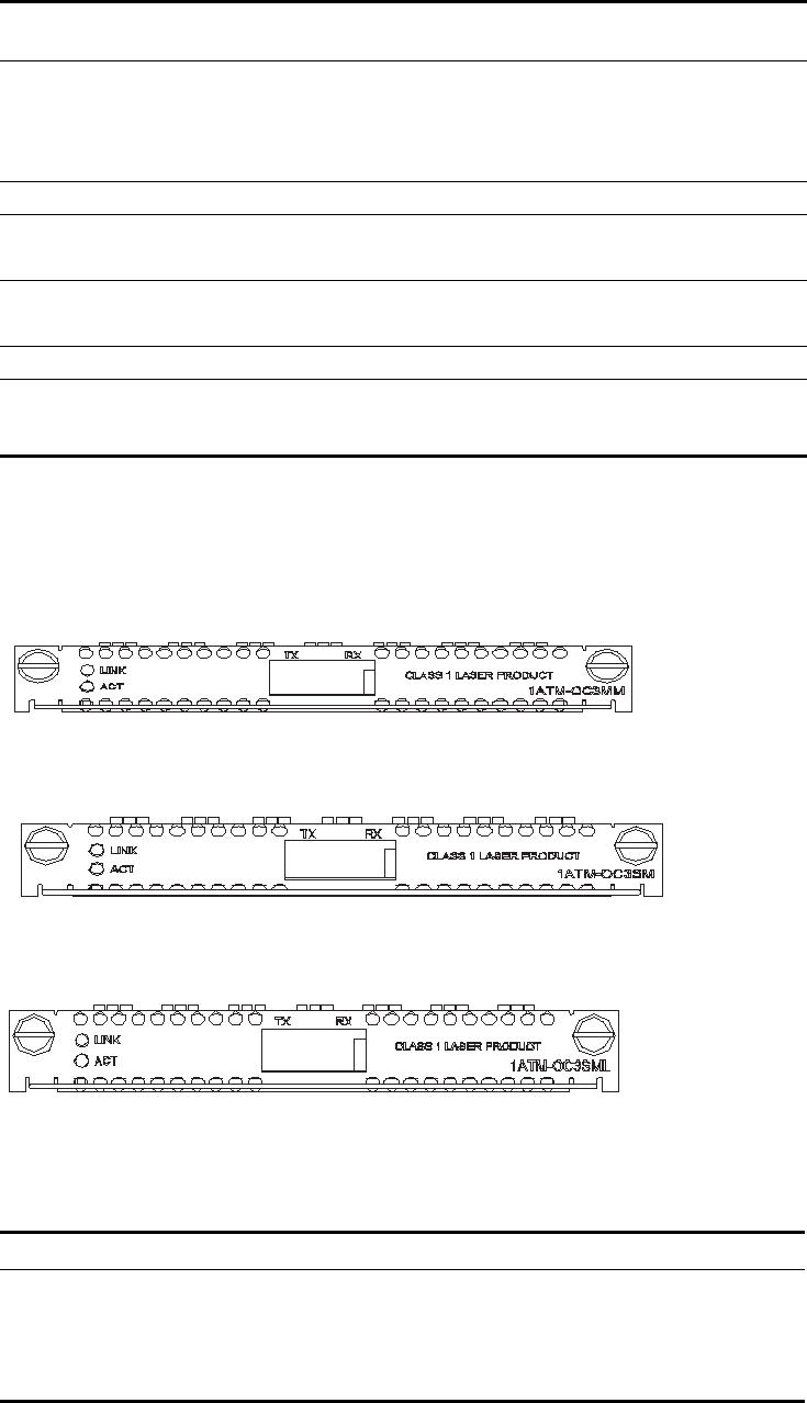
Interface LEDs MIM-1AMM/MIM-1ASM/MIM-1ASL module panels are shown in the following
figures:
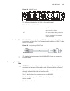
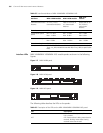
Figure 117 MIM-1AMM panel
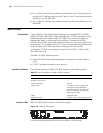
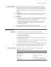
Figure 118 MIM-1ASM panel
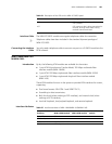
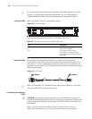
Figure 119 MIM-1ASL panel
The following table describes the LEDs on the panels:
Cable type and the
maximum transmission
distance
Multimode optical fiber
of 2 km (1.2 mi.)
transmission distance
Single-mode optical
fiber of 15 km (9.32
mi.) transmission
distance
Single-mode
optical fiber of 30
km (18.6 mi.)
transmission
distance
Transmitter LED Laser Laser
Transmission optical
power
Min: -21 dBm
Max: -14 dBm
Min: -15 dBm
Max: -8 dBm
Min: -5 dBm
Max: 0 dBm
Receiver sensitivity Min: -28 dBm
Max: -8 dBm
Min: -30 dBm
Max: -14 dBm
Min: -34 dBm
Max: -10 dBm
Central wavelength 1310 nm
Service ATM Traffic CBR (Constant Bit Rate), rt_VBR (Variable Bit Rate-Real
Time), nrt_VBR (Variable Bit Rate-Non Real Time), UBR (Unspecified Bit
Rate)
Table 65 Interface attributes of MIM-1AMM/MIM-1ASM/MIM-1ASL
Attribute MIM-1AMM module MIM-1ASM module
MIM-1ASL
module
Table 66 Description of the LEDs on the MIM-1AMM/MIM-1ASM/MIM-1ASL panel
LED Description
LINK OFF means no link is present; ON means a
link is present.
ACT OFF means no data is being transmitted or
received; blinking means data is being
received or/and transmitted.