


MIM-2SAE/MIM-4SAE/MIM-8SAE Module 75
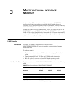
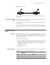
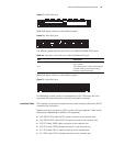
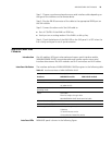
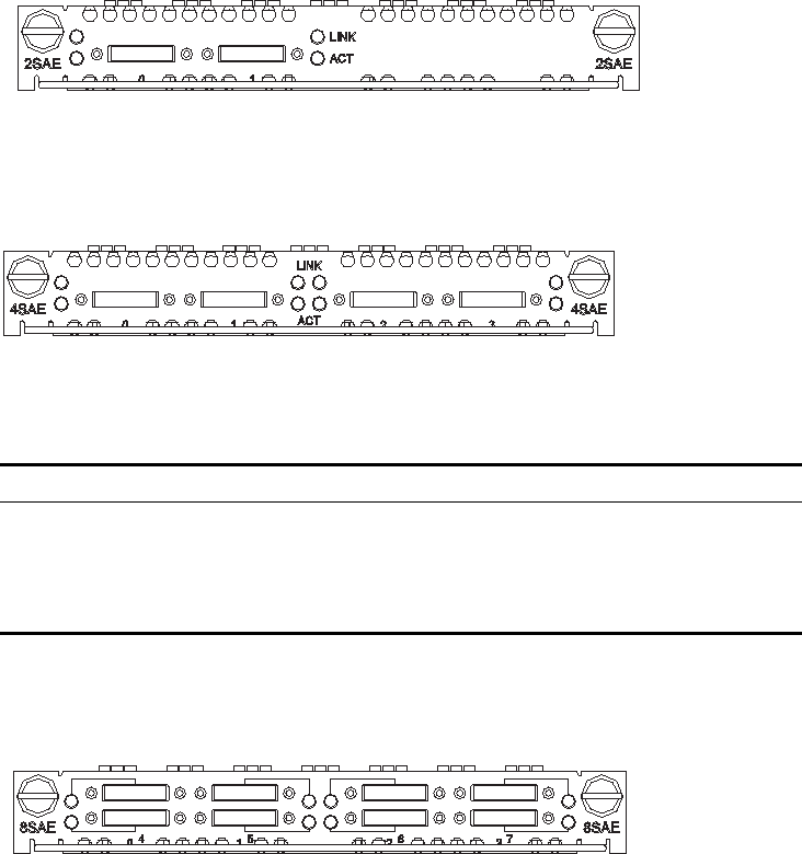
Figure 73 MIM-2SAE panel
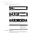
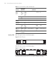
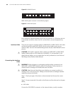
MIM-4SAE panel is shown in the following figure:
Figure 74 MIM-4SAE panel
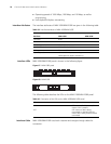
The following table describes the LEDs on the MIM-2SAE/MIM-4SAE panel:
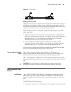
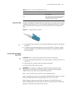
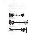
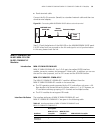
MIM-8SAE panel is shown in the following figure:
Figure 75 MIM-8SAE panel
On MIM-8SAE module, each link corresponds to a LED. ON means the link is
connected. Blinking means data is being transmitted or received.
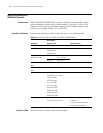
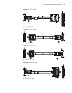
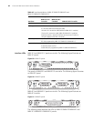
Interface Cable SAE modules use synchronous/asynchronous serial interface cables with DB-28
connectors for connection.
Before connecting to a port on 2SAE, confirm the line properties. There are ten
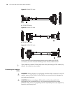
cable options depending on different line properties:
■ V.24 (RS232) DTE cable: DB-25 (male) connector at the network end
■ V.24 (RS232) DCE cable: DB-25 (female) connector at the network end
■ V.35 DTE cable: 34PIN (male) connector at the network end
■ V.35 DCE cable: 34PIN (female) connector at the network end
■ X.21 DTE cable: DB-15 (male) connector at the network end
■ X.21 DCE cable: DB-15 (female) connector at the network end
Table 44 Description of the LEDs on the MIM-2SAE/MIM-4SAE panel
LED Description
LINK OFF means no link is present; ON means a
link is present.
ACT OFF means no data is being transmitted or
received; blinking means data is being
received or/and transmitted.