


192 CHAPTER 4: FLEXIBLE INTERFACE CARDS
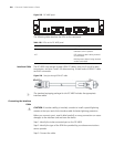
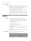
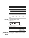
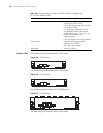
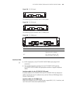
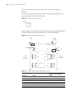
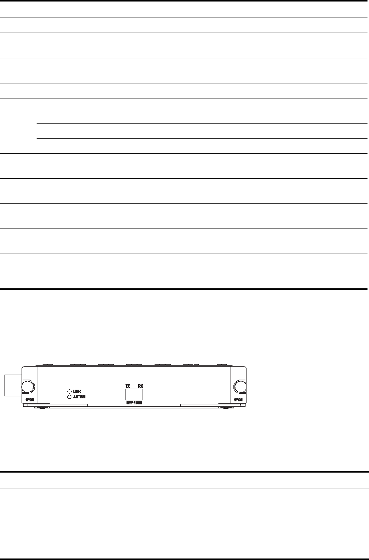
Interface LEDs The following figure illustrates the FIC-1POS panel:
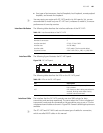
Figure 234 FIC-1POS panel
The following table describes the LEDs on the FIC-1POS panel.
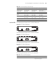
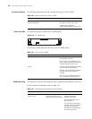
Interface Optical Fiber Like the FIC-1CPOS, the FIC-1POS uses optical fibers with LC-type connectors.
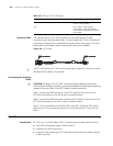
Connecting the Interface
Optical Fiber
Step 1: Insert the SFP card into its corresponding slot.
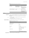
Table 137 Interface attributes of the FIC-1POS
Attribute FIC-1POS
Connector SFP/LC
Interface
standard
SONET OC-3/SDH STM-1
Number of
interfaces
1
Interface rate 155.52 Mbps
Optical
transmi
tter
power
Type Multi-mode
short-haul
Single mode
medium-haul
Single mode
long-haul
Single mode
ultra-long haul
Min. -19.0 dBm -15.0 dBm -5.0 dBm -5.0 dBm
Max. -14.0 dBm -8.0 dBm 0. dBm 0. dBm
Receiver
sensitivity
-30.0 dBm -28.0 dBm -34.0 dBm -34.0 dBm
Overload optical
power
-14.0 dBm -7.0 dBm -9.0 dBm -10.0 dBm
Central
wavelength
1310 nm 1310 nm 1310 nm 1550 nm
Fiber type 62.5/125 μm
multi-mode
9/125 μm single
mode
9/125 μm single
mode
9/125 μm single
mode
Max.
transmission
segment
2 km (1.2 mi.) 15 km (9.3 mi.) 40 km (24.9 mi) 80 km (49.7 mi)
Table 138 LEDs on the FIC-1POS panel
LED Description
LINK OFF means no link is present; ON
means a link is present.
ACT OFF means no data is being
transmitted or received; blinking
means data is being received or/and
transmitted.