


232 CHAPTER 5: ESM/VCPM MODULE
Interface Attributes
Interface LEDs There is no LED on the VCPM card and display of the status of the module is
implemented through the VCPM interface LED on the main board of the router.
The following table describes the LEDs on the main board:
Installing/Removing
VCPM Card
VCPM card should be installed on the main board of the MSR 30 router and on
the VCPM slot on the MSCA card of MSR 30 router. The board that provides
VCPM slots is referred to hereafter as mother board. Suppose the mother board is
uninstalled and put on the workbench.
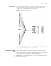
Removing VCPM card
Follow these steps to uninstall the VCPM card:
Step 1: Remove the three fastening screws on the VCPM card.
Step 2: Remove the VCPM card from the mother board. Do not overexert when
removing the VCPM card because the connector of the daughter board is still on
the mother board.
Step 3: If no SNDE card is to be installed, remove the three metal standoffs
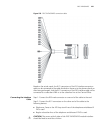
Installing VCPM card
Follow these steps to install VCPM card:
Step 1: Confirm the correct position of the VCPM card on the mother board.
Step 2: Fasten the three metal standoffs on the mother board.
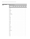
Table 175 Interface attributes of the VCPM module
Attribute Description
Connector Double-edge connector
Interface type PCI 2.2, EHPI
Data transmission rate Operating rate for PCI bus: 33 MHz/66
MHz
Maximum bandwidth: 264 Mbps
BURST transmission: Up to 1 KB of
data can be transmitted once and the
maximum number of bytes
transmitted can be configured.
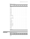
Table 176 Description on the LEDs
LED Description
VCPMx Green: VCPM card is in the slot and is operating normally.
Yellow: VCPM card is in the slot but cannot be accessed by the router.
Note:
X means the slot number VCPM card LED is on.